Last March while preparing multiple backyard antennas for the Virginia QSO Party, I needed a way to use just one coax out to the back yard. A coax switch was in order. Cash is always limited and I was seriously thinking about the Ameritron products… especially the four port model that does not need a separate control cable. However, I read some reviews suggesting the Ameritron RCS-4 works fine, but has leakage to the un-selected ports albeit small. I continued to search for switch and remembered DX Engineering has some models to consider. I have purchased other DX Engineering products and find them excellent.
The specifications for their eight port RF switch suggest less leakage of RF to the unselected ports. The construction of the switch appeared to be the usual robust construction DX Engineering is known for. I made the purchase and put it to immediate use for the QSO Party.
Now it is August and I am finally getting around to reviewing the DX Engineering RR8-HP eight port coaxial switch and the controller.
The review will be two articles: initial thoughts, photos and then bench RF testing.
Initial thoughts:
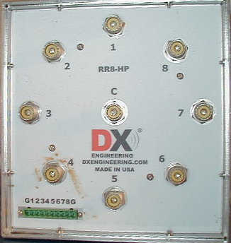
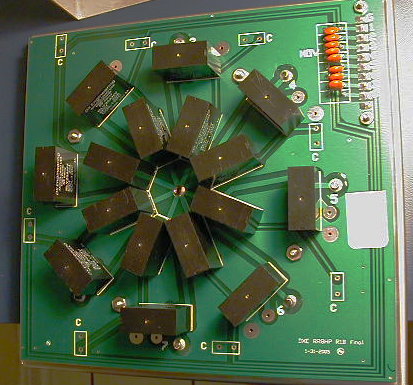
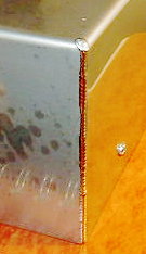
This is one sturdy piece of equipment. It is made of Stainless Steel with a circuit board inside which performs the actual switching function. The electronics is housed in an upside down box with welded edges to make a rain resistant box. The coaxial connectors face down. Details include:
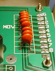
- MOV Protection on each control input
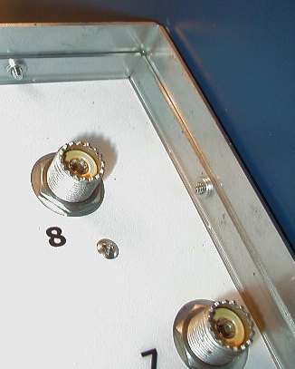
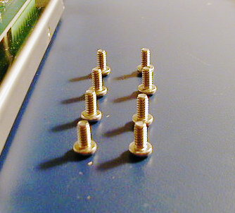
- Real machine screws, not sheet metal screws, used to hold everything together – very nice
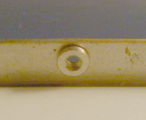
- Deep threaded inserts for the machine screws to thread into
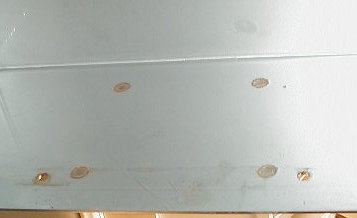
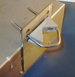
- Four spot welds to hold the mounting flange to the box
- The relays appear to be a custom model with “RLY20AHV, SPDT, 20A, 12VDC Coil” imprinted on the side
- Two relays in series for each channel helps with isolation
- Optional shorting of unused channels
- The face plate with the connectors is the ground connection for the shield currents
- Two layers circuit board with thickness of the usual 62 mils
- RF conduction paths on circuit board are about 100 mils wide and are on both the top and bottom of the board to share the currents
- Relay control signal copper width about 1/20″
- Ground plane used on both sides of the board – appears to be used for grounding the unused channels (with optional shorting braid installed) and for the relay coil return current – This provides an opportunity to place 1 MΩ resistors instead if all you care about is static dissipation.
- Vias in the circuit board join the top and bottom ground copper pours – However, some of the vias are not fully attached to the surrounding copper
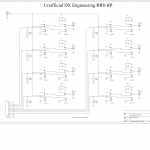
For some reason DX Engineering does not include schematics in their product manuals like most any other amateur radio product. However, it is not too difficult to figure out. A best guess is included below.
I can say I have never seen a better engineered amateur radio product on this level from any other company. Despite the higher cost of this product, vs. competitors, it is clear to see this is the far better value.



Nice mechanical design. But relays fail often at 1.5 KW. I have lost 5 of them over the past 3 years, and they are a pain to replace. Their so called 20 amp relay is really to 10 amp contacts in parallel. That is most often called by other manfuctures a 12/16 amps relay at DC, not RF. My failures are at 1.5 KW or lower not 5KW as their spec indicates indicates they can handle. I think they forgot that relay specs at DC are not the specs at 30 MHz. All my failures have been above 21 MHz.