Common mode current suspicions
Various tests of the venerable N9TAX dual band ladder line J antenna suggest the coax becomes rf hot at UHF. It was time to quantify this behavior in the lab.
Sacrifice
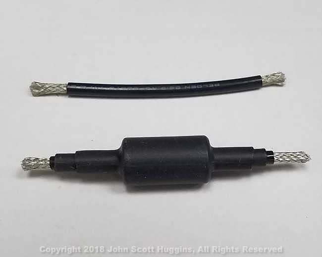
Yeah it brought a tear to my eye, but I cut out the ferrite choke from my MURS/GMRS N9TAX ‘Slim Jim’ J antenna for the purposes of measuring the common mode attenuation it provides. The next figure shows the ferrite with its coax along with a similar length of RG-58 for comparison.
Tracking generator test
A portable VNA was configured to measure S21 using the arrangement of bananas in figure 2.
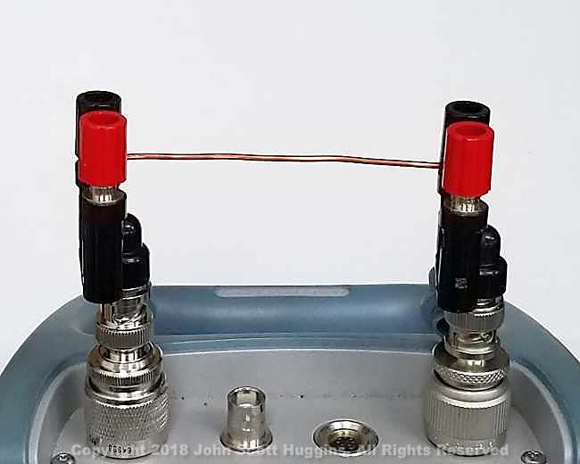
The instrument was configured to sweep from 10 to 500 MHz. At some point the distance between the test points becomes a sizable fraction of the wavelength, but let’s see how it goes.
Test of straight piece of RG-58
I swept the piece of RG-58 and used it for calibration so we get a decent A/B comparison of coax with and without the ferrite used by N9TAX. Calibration complete, the coax with ferrite was swapped in place.
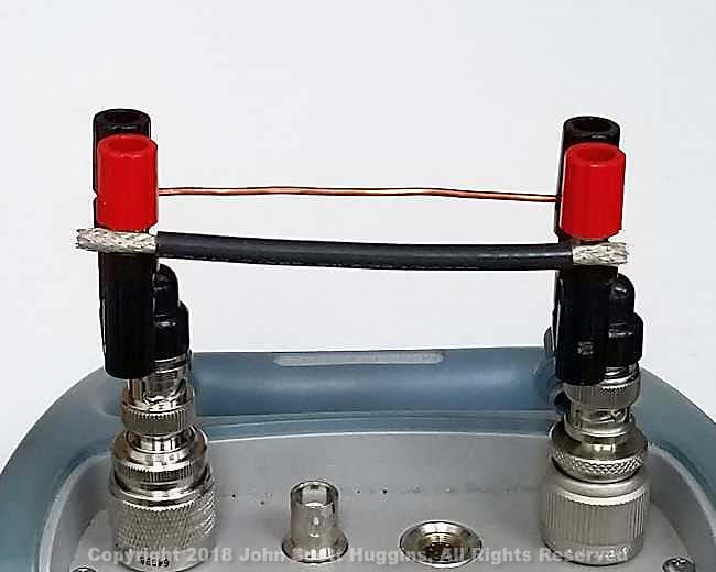
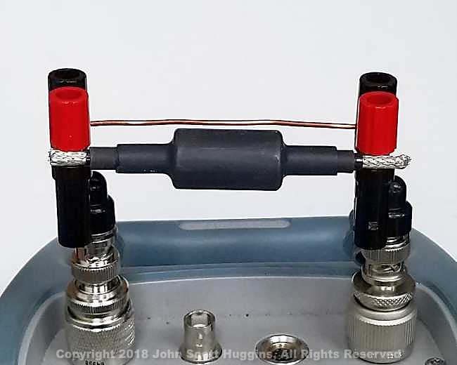
Puzzling why I’m not measuring coax loss via the center conductor and shield? Common mode currents typically don’t include the otherwise balanced and opposite currents within the coax and usually run along outside the shield at HF and VHF frequencies. So really we are simply treating the RG-58 as a large diameter wire. Indeed if we substitute a #10 copper wire for the coax the results will be the same.
S21 test results of N9TAX ferrite choke
Figure 5 contains the results of the ferrite test with arrows highlighting values at VHF and UHF amateur radio spectrum segments.

Since the plain coax was also our calibrator, its transmission in green shows a nice flat line from 10 to 500 MHz. The power attenuation observed through the ferrite in red is what one should expect. With a logarithmic frequency axis we see a more balanced slope on either side with a more textbook shape.

Ferrite attenuation at 2m
The ferrite provides almost 90% power attenuation for the 2m band. Sure it could be better, but this should be decent enough to quell “most” of any feedline common mode currents stimulated by an antenna’s design. Could it better? K9YC sure thinks so, but sometimes “the best is the enemy of the good.”
Ferrite attenuation at 70cm (440)
The ferrite still provides over 50% power attenuation for the upper end of the 70cm band. Is that enough to manage feedline currents? Perhaps or perhaps not, but the prudent among us should wear expressions of concern lest feedline common mode currents, albeit at less than 1/2 power, ruin a perfectly good antenna pattern.
But this is about common mode ‘current’ right?
Note this is a relative power measurement. The current attenuation for a given common mode circumstance drops by the square-root of power. This means this ferrite’s ability to mitigate common mode current is even worse than the graph suggests. Per the suggestion from a commenter below, the following graphs (added Sept. 22) portray the same concepts, but in percentage current calculated by converting a normalized current (because I have no idea what power the VNA uses for its tracking generator) into measured current using the P = I^2 * R and assuming a 50 ohm impedance. Here we go…
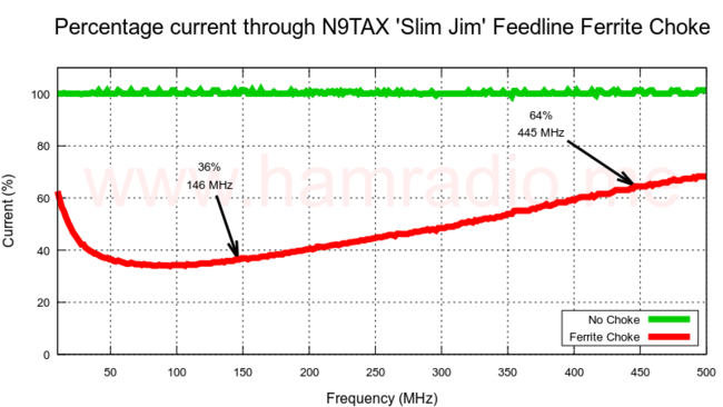

The squiggly green line of course shows 100% by definition, but isn’t perfectly straight as a reminder that real data often has real noise and to give the reader some understanding of data uncertainty. As you can clearly see, the data uncertainty is much less than the larger trends shown by the ferrite under test.
Remember, this data is NOT measured by a current sensor. It is derived from S21 power measurements.
Assuming a 50 ohm impedance?
For testing like this we can likely assume for calculations a 50 ohm system impedance. In the real world the current to power relationship will be a bit different. In many of the diagrams you find on this site, I’ve generalized impedance points along antennas, feeds, etc. as Hi and Lo Z to help maintain the notion impedance is often used as a relative term than precise metric. We must keep in mind measuring power through a choke requires knowledge of impedance to calculate current.
This is just one ferrite choke example
What is the ferrite material used in the N9TAX products? The sent email with that question remains unanswered. At least these measurements help understand the actual behavior so we don’t have to guess any more.
It is vitally important for the antenna user to understand there are many flavors of ferrite material. Paired with how you apply the available ferrite products yields designs benefiting specific frequency ranges and uses. No one ferrite-construction topology is good for all frequencies and purposes. K9YC does as good a job as any on the various recipes and techniques available to help the antenna user make educated choices for particular circumstances. I built the choke for the AHVD Antenna using his suggestions and it works stunningly well. Recommended reading…
A Ham’s Guide to RFI, Ferrites, Baluns, and Audio Interfacing
Conclusion
The ferrite used in this antenna appears to good for VHF only. It appears to have some utility above VHF, but you’re going to need more than one in series or apply other advanced ferrite methods. Given the data above, three in series for UHF might be enough to equal what one provides for VHF.
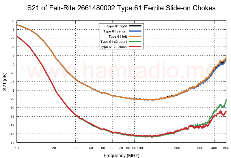
Fair-Rite offers potentially more pragmatic hope with their Type 61 material…
Snap one of these 200-1000 MHz clamp-ons above the stock N9TAX ferrite choke to add 300+ ohms more series resistance to common mode current at UHF, and you may well have a near perfect dual-band antenna. K9YC would say you should aim for much more series resistance and he is certainly correct. It’s up to you to decide what is good enough for a portable 2m/440 antenna.
Interesting and educational. Thank you for sharing this.
Ok, this shows attenuation with the ferrite, as expected. What I was expecting was a measurement of common mode current, with and without the choke. How do you know the ferrite is being effective, if you don't know what the common mode current is? Inquiring minds want to know…
DaveL
KF7JAF
Hmmm, well I can convert the S21 measurements to amperage as a percentage. Let me see what I can add.
I do not see a new measurement with the added ferrite–does it work?
Steve