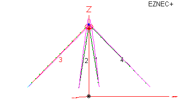
In a previous post I discussed the attributes of using two dipoles arranged ninety degrees from each other and mounted in an inverted V configuration. If fed with RF energy in quadrature, one signal delayed ninety electrical degrees from the other, you have a form of turnstile antenna.
Turnstile antennas are provide circular polarization straight up and at large angles from zenith. Originally I was going to just connect the two antennas together at my switch so I could select one, the other or both. The electrical delay would be provided by one longer feed line. However, one attribute considered essential by the scarce resources on the Internet insisted on switchable polarization: RHCP to LHCP and back by simple inverting the connection to ONE of the antenna feed lines.
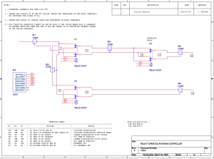
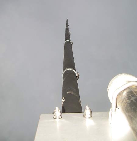
With these thoughts I changed the plan a bit. Instead of using my switch and two very long feed lines, I now have one single feed line from the switch to the base of my 50 foot high antenna mast. Here I will provide a relay box with three relays, one coaxial cable in and two coaxial cables out. The two output coaxial cables will each feed one 75 meter dipole on the antenna mast. One cable is ninety electrical degrees longer than the other.
Here is a schematic of the relay box…
All this will be going into a weather proof enclosure with cables directly connected to the relays where noted.
What about perfect matching John?
I am not too worried about the perfect 1:1 SWR for this setup. In fact I don’t worry much about SWR under 3:1. The impedance presented to the radio side coaxial cable will be the two antennas in parallel although I admit I am not quite sure how these signals combine if they are ninety degrees different in phase. I forgot to look at that in EZNEC. I do remember it was not too high.
In another post I will show some photos of the resulting assembly.


Any update on the SWR ??