Mag Mounts. Bum Rap?
Over the years I have heard amateur radio folks, CBers and scanner fans bash the use of magnetic mount antennas. Concerns include flying off the vehicle and becoming a projectile during an auto accident. Other concerns relate to performance and stem primarily on how well the shield of the coax is electrically connected to the conductive body of the car.
I cannot comment on the mechanical realities of the antenna flying off the roof during rapid changes in speed, but can say I have never seen one do so. I encourage anyone with data to propose their article to this web site
So…
Addressing the Mag Mount Electrical Questions
Let’s talk about the electrical conductivity of a standard mount vs. a magnetic mount antenna. Here is a quote from the newsgroups concerning antennas for scanners…
The average mag-mount antenna gets its “ground” from the magnetic attraction between the mount and the metal of the car body. This is nowhere near the quality of a good, solid ground connection to the body. We are relying here on the mount, the paint on the car, and the metal underneath to form a “capacitive ground connection”. (I scared myself with that one !) The smaller in diameter the magnetic mount is, the less effective this is. It is a simple matter of total area covered by the mount.[1]
The post author correctly identifies the ground connection happens due to the capacitor created between the bottom of the antenna and the metal of the vehicle. The claim this is worse than a direct connection via set screw or other demands verification. Let’s do some math to check this out.
First some assumptions:
- Paint thickness of autos seems to range from 75-200 microns. Add in clear-coat and primer this might grow to 3x or so. I am not a paint guy so I am not at all sure about these figures, but since capacitance is reduced at greater thickness, we will assume 600 microns for our calculations or about 24 mils (1 mil = 1/1000 inch).
- Typical small 2m ham antenna with 3 inch base.
- Braid of coax electrically attached to the foil on the bottom of the antenna. Did you notice that mag mount antennas have electrical foil to make the antenna side of the capacitor?
- We will derive the capacitive reactance of the above details at 50MHz, 144MHz and 440MHz
- Dielectric Constant, K, of clear coat and paint something like 3
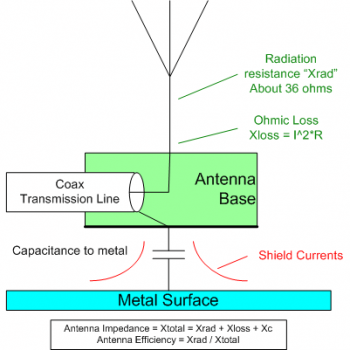
Figure 1 shows a simplified model of antenna electrical parameters:
- The Radiation Resistance is the thing you want your transmitter to work into.
- The Ohmic loss is the simple resistive loss of the antenna and its inner connections.
- The sum of the Shield Currents exactly equal the current on the inner conductor and flow back to the transmitter on the inside of the outer conductor. If you do not connect the antenna’s ground to the local ground around the antenna, the current will simply flow back on the outside of the outer coax conductor potentially creating havoc for your radio and possibly you.
- This fact applies equally well to ground mounted HF vertical antennas and is why radials are so important.
- Xc is actually part of the impedance from coax shield to ground and adds directly to the overall impedance.
- Keeping every resistance or impedance small with respect to the radiation resistance makes or breaks an antenna’s efficiency.
Calculating Capacitance between Antenna and Metal
The formula for the capacitance between two conducting plates is:
C = 0.2258 * K * A / d
Where…
- K is the dielectric constant of the material,
- A is the overlapping surface area of the plates in square inches,
- d is the distance between the plates in inches, and
- C is capacitance in pF (pico Farads – 1×10-12 Farads)
Capacitor Area = pi * r^2 = 3.14159 * 1.5^2 ~ 7 sq. in.
Capacitance(pF) = 0.2258 * 3 * 7 / 0.024
Capacitance(pF) = 198pF
Xc = Capacitive Reactance = 1/(2*pi*f*C)
Results:
- When f = 50MHz => Xc = 16 Ohms
- When f = 144MHz => Xc = 6 Ohms
- When f = 440MHz => Xc < 2 Ohms
This probably represents the worst case where the car’s paint and clear-coat are super thick as assumed above. Let’s redo the calculations for a more probable 8 mils…
Capacitance = 0.2258 * K * A / d
Capacitance(pF) = 0.2258 * 3 * 7 / 0.008
Capacitance(pF) = 593pF
Xc = Capacitive Reactance = 1/(2*pi*f*C)
Results:
- When f = 50MHz => Xc = 5 Ohms
- When f = 144MHz => Xc < 2 Ohms
- When f = 440MHz => Xc < 1 Ohm
The above calculations reveal mag mount antennas do, indeed, provide a very robust AC coupling of the RF shield currents to the metal of the car via currents through the capacitor.
The impedance presented by the mag-mount/metal interface adds directly to the radiation impedance of the antenna resulting in the final impedance of the antenna approaching 50 ohms… ~36 ohms + Xc. This also directly affects the efficiency of the antenna just like a ground radial system helps a ground mounted vertical.
The post author does understand the area of the mag mount bottom in contact with the car matters with larger being better. He goes on to say…
I am not going to launch into a big tech discussion here, with foot-long words, and math that would give you (and me) a headache. You will just have to take my word for it. And, the really sad part is, the higher the frequency that you monitor, the worse this gets.
This is where his understanding breaks from reality. The higher the frequency the better. The math is straight forward; You do not have to take anyone’s word for it. All other things being equal, capacitors conduct better at higher frequencies as the above math shows. There is no need for foot-long words, but full understanding does require doing some math.
Results
What we have shown above is magnetic mount antennas do, indeed, provide a good connection to the metal it is attached to so long as there is a foil bottom attached to the shield of the coax and the area of this bottom is reasonable large. It is true that as the frequency goes down, the mag mount antenna efficiency also goes down. Many CB antennas for 27MHz have much larger bases not only to support the longer whips, but to provide that extra contact area to keep the Xc low.
It can be argued this large capacitor in contact with the metal of the vehicle may well be more effective than trunk lip mounts that make their contact with one or two small set screws dug through the paint to the metal of the trunk lid or gutter. This is, of course, if the trunk lid is made of a conductor… many are not. This is all especially true if high power is applied to the antenna system. The magnetic mount antenna provides the unique advantage of spreading the ground currents over a large area rather than through the finite points of locking screws.
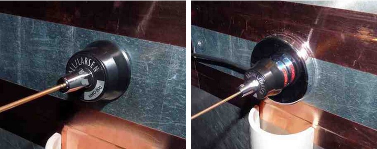
A properly installed through-hole NMO mount probably beats the mag mount in shield to ground plane connection as its design provides a large direct contact area from shield to hole avoiding the set screw problem.
When shopping for a magnetic mount antenna you might well benefit from a unit that keeps the Capacitive reactance below, say, 10% of the antenna impedance. For a quarter wave antenna of about 36 ohms that suggests the mag mount impedance should be under 3 ohms. Much depends on the frequency, paint thickness, dielectric constant and area. Armed with the above technique you can comparison shop with better clarity.
Conclusion
With the above method of calculation, you can easily convince yourself that, at least electrically, the magnetic mount antenna works just fine in many situations and provides the added bonus of putting the antenna in the best position without need for a hole in the roof.
References:


Excellent article. Thank you!
Isn't the thickness of the capacitor both the paint on the car and the rubber on the mag mount (the later being much thicker?)
Most mag mounts I have and seen have a thin metallic conductive foil between the magnet and the car. It's true the perimeter of the base may be plastic and touching the car, but the magnet of most antennas I've seen is strong enough to squeeze the conductive foil firmly against the metal of the car. You have apparently found a model that has some sort of covering over the entire bottom of the antenna. Indeed, the capacitance will be less.
I applied a big (maybe 6") round sticker of sticky backed high performance vinyl (about the thickness of a sheet of thin paper) sign lettering to my car where I placed my CB radio mag mount antenna. I still tuned a very useable SWR on the whip antenna. I'm sure it very slightly reduced the antenna performance. I think it was more noticable on receive sensitivity, but was perfectly useable. It was worth it to me (at the time) to avoid scratching the paint on my car when placing or removing the antenna. I also think the slight cushion effect helped hold the mag base solidly in place. I never pealed off the vinyl, and it went with the car when I sold it. No scratches.
hola en estos tiempos de cuarenta por coronavirus necesito convertir mi antena magnetica para usarla en mi pequeño apartamento y usarlo en un pequeño mastil que tengo de 3 metros, que ideas me pueden compartir para poner el plano a tierra ? muchas gracias
Here is a thought: If the radio is wired back to the car battery then the coax braid will be connected to the car earth through the radio chassis. This is not a low resistance route, but it does add significantly to the earth efficiency.