The previous post covers how I stumbled onto the LNR Precision EF-10/20/40 multi-band portable HF end fed antenna examining mine closely and even going so far as to rip the well sealed cover off the matchbox to see what’s inside.
The LNR manual discusses some antenna mounting arrangements.
This post covers the test setup and resulting data of the EF-10/20/40 hung simply in a tree as a mostly vertical antenna.
Measurements of SWR and Return loss are the focus of this test. I really wanted to see how well that matchbox assembly did its thing. Eventually I will actually operate with this antenna, but, as I mention in the previous post, operating behavior is quite dependent on a great many variables beyond antenna performance. The E-Ham reviews suggest this antenna does “get out.”
The focus here is measurable antenna metrics: SWR and Return Loss. Measurements were made of the:
- Antenna System,
- Sensitivity of the Matchbox to nearby objects,
- Bandwidth of the matchbox
- Behavior of the matchbox without the capacitor.
Test Setup
Figure 1 reveals the simple back yard test setup.
The left picture shows my antenna analyzer sitting on the cement lid of a convenient concrete platform. A peg to the left holds a piece of yellow mason line which goes over the bird feeder stand to the matchbox.
The center picture of Figure 1 shows the matchbox happily floating in the air suspended by the antenna wire and the mason line. A short length of RG58 hangs under the matchbox running to the antenna analyzer. The antenna wire pulls away from the matchbox at a shallow angle, but curves to the tree top in a gentle sweep.
The right picture of Figure 1 shows pretty much nothing. The almost invisible black wire antenna hangs from a rope thrown over the 50 foot maple tree.
The following data comes from the above arrangement.
SWR and Return Loss Measurements at 40, 20 and 10m
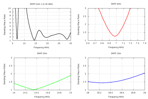
Figure 2, above, shows four SWR measurements: One big sweep from 5-30 MHz (black), 40m (red), 20m (green) and 10m (blue) plots. The plots are self explanatory and show this antenna does exactly what it says it will do.
Note the 40m red plot is a little low in frequency thanks to LNR providing an extra few inches in the wire beyond the choke inductor. This is purposely part of the product to provide flexibility in tuning should the environment need the extra length. As you can tell, my backyard setup reveals the need for trimming, but I left as is for these tests.
The antenna loads quite well at 20m and 10m,
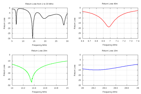
For the professional antenna folks and antenna aficionados out there, here is the same data as Return Loss…
The above graphs reveal this antenna certainly does absorb energy in the 40m, 20m and lower 10m bands. The Return Loss graph confirms the best match is in the 20m band.
Matchbox Sensitivity Test
There are drawbacks to Feeding a half-wave antenna at the high impedance end. One is the sensitivity of antenna endpoints to nearby objects thanks to high voltage coupling. Figure 1 shows the matchbox six feet above ground, well away from any interfering objects. A quick wave of the hand near the matchbox greatly perturbed the readings on the antenna analyzer. Examining this phenomena closely, the following Figures 4, 5 and 6, show what happens to the Return Loss (better than SWR for this kind of analysis) when 6 feet up (red), one foot above ground (green) and laying on the ground (blue).
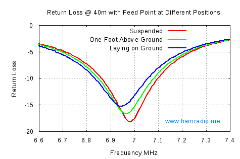
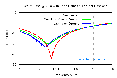
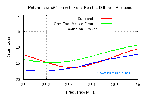
While not tremendous, the detuning effect is certainly noteworthy. Note how the bandwidth broadens when close to ground. The Q of the antenna is lower which happens with additional resistive losses in the system. Resistive losses reduce antenna performance. One should view this resistive loss as energy leakage into ground where it cannot help your signal. From what I see here, I will endeavor to keep that matchbox and the high voltage end of the antenna well above ground because ground is a variable I can easily remove by elevating both.
In the previous post, LNR EF-10/20/40 Examination, the topic of counterpoise occurs often. While my “hand-test” reveals measureable sensitivty near the matchbox, running my hand down the feedline to the antenna analyzer has a very small effect. More research may help define just what the counterpoise is for this system. I’ve handled many antennas looking for extra currents on the feedline; This one seems to keep these currents to a minimum.
Bandwidth vs. Load Test
In figure 4 of the previous page we see the matchbox is little more than a transformer converting between 50 ohm coaxial cable and the one to five thousand or so ohms impedance one finds at the end of a half-wave antenna. This particular antenna model is multi-band suggesting the transformer works over a rather wide range of frequencies.
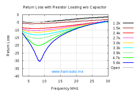
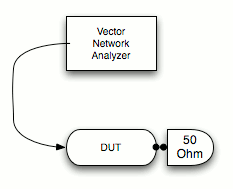
The next test setup removes the antenna wire and replaces it with a non-inductive resistor between the antenna terminal and the shield of the coaxial cable. I choose several common values of resistance plus “open” for the data shown in Figures 7 and 8…
This test is a bit oversimplified, but confirms the antenna manual’s assertion it will drive a half-wave antenna end load from 60m to 10m.
The purpose of the Capacitor in the Matchbox
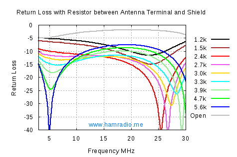
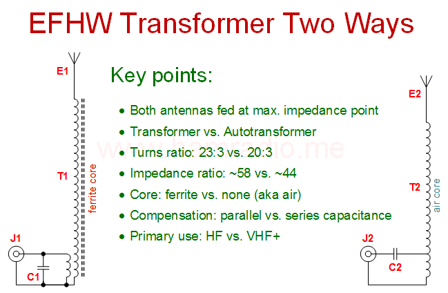
I suspect the capacitor across the 50 ohm side of the matchbox compensates for the inductance of the transformer portion. That’s only my opinion for now and you know what those are worth. Figures 9 and 10 show the same resistor test with that capacitor removed from the matchbox.
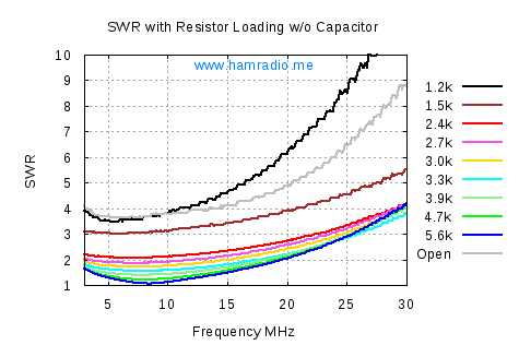
The capacitor across the SO-239 connector obviously plays a very important role in this impedance transformer design. Judge for yourself. I’m soldering the capacitor back in.
Conclusion
Electrical Design
The EF-10/20/40 antenna is a perfect blend of a 40m/20m Choke antenna and an elegantly simple end fed transformer design. Operating the 20m element as a 10m full wave rounds out this antenna to three useful bands for the Amateur in one assembly.
Using the coaxial cable and the radio as the counterpoise is a smart move.
The broadband design of the match box with its toroid transformer and capacitor comes at a cost of max power handling. The design can certainly scale upward to handle more power, but for portable QRP use, this antenna model is perfect.
Mechanical Design
Nothing about this antenna design cannot be done by the average Amateur. Many hams suggest this antenna is far too expensive for what it does. The question to ask is if this particular product provides commercial quality features not easily available to the home-brewer. The answer is a solid Yes. From the well sealed transformer box (with sturdy hardware and rope mounting points) to the choke inductor (with slick inline terminal connections) to the kink-resistant antenna wire itself, this product shows well thought out refinements any Amateur will appreciate.
Materials
The plastic material in the transformer block is thick, sturdy and light. The clear glue within looks a bit crude, but gets the job done. The insulation on the antenna wire and the wire itself behave terrific when deploying or packing.
Final Thoughts
The LNR Precision EF-10/20/40MKII Antenna is a winner in my “lab” book. Time will tell how well it functions in the field, but nothing looks to prevent this antenna functioning as well as any antenna of similar length.
Whereas 40m and 20m are halfwave antenna modes with this antenna, the 10m operation is full-wave. This means there will be directional lobes in headings and elevation dependent on how you deploy the antenna. Simulation and experimentation can help understand how this plays out. I’m not sure this makes much difference since when 10m is open it is often open big where wet noodles work well.
The power limitation of this antenna works well for my QRP needs. Those running 100 watts need to look elsewhere such as the HyEndFed Multi-Band EFHW models or the single band Endfedz from LNR Precision.
Other bands are available by replacing the radiator with your own half-wave wire.
For as portable as it is, this is a remarkably handy backpackable multi-band antenna I’m glad to own.
73,
John, kx4o



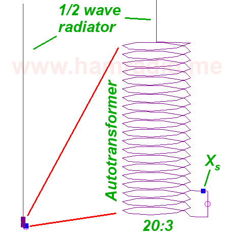
The matchbox is not difficult to homebrew. 3 turns primary & 27 turns secondary of #22 magnet wire. The toroid is an FT82-43. Order the potting box from polycase.com or similar outfit. The matchbox will tune any wire cut to an HF band. I have used it with 80m – 10m. It works great up to 25 watts or a bit more with CW. I have found that it does not work well after a few minutes with digital at 25 watts – SWR goes bonkers (overheating the matchbox?). 73…
Thanks for the information Ed. What would you suggest to upscale the toroid to handle 100 Watts and/or handle lower power with digital?
Hamradiome,
Have you ever figured out what it take to upgrade a home brew EFHW LNR Precision EF-10/20/40MKII to handle 100 watts?
Not yet Tim, but I I have some ideas.
If Ed is correct about the toroid material, then a larger version of that toroid will be a starting point for a new design. I suspect a larger toroid with the same winding ratios will have different band pass characteristics, but this can be mitigated through some trial and error using my resistance measurements as a reference. This assumes, of course, the toroid, acting as an actual transformer passing all the power, is the limiting factor. The capacitor is likely to be more so, but am just not sure. Upgrading both is the likely result.
I'll take on the task of a higher power version of this, but won't likely get to it for a month or two. I think we all agree the form factor of this design is very nice and worth translating to higher power levels. Who knows, maybe LNR has a higher power version in the queue.
John
Thanks John, great report, just ran across it today from your post on the KX3 reflector. In spite of one reply on there, I think your resistor tests show it really is transformer action in play.
Any progress on the 100 W version? I'd be a little concerned that stray "counterpoise" currents may become menacing.
The resistor tests certainly suggest transformer action. I'm a bit surprised at how well the transformer math holds up for this LNR example. I expected a bit more deviation from theory as real world losses come into play. This test was a pleasant surprise.
I haven't made progress on the 100W version. I'm still working towards a portable radio.
John
I'm wondering why they use a choke at all. Would it not work to use one ~66 ft long wire for 40, 20, 15 and 10 m, which would be 1, 2, 3, and 4 half-waves long?
One reason is to keep the 20m working as a single half-wave and the 10m as full-wave rather than full-wave and 2 wavelengths respectively. Either will work, but the 10m will take on a more complex pattern shape at 2 wavelengths.
One nice thing about the LNR transformer box is you can try other wires so long as they present a high impedance, say 2400 ohms or more, to the antenna terminal.
John
That's correct about the 10M pattern. Even at one wavelength, the pattern becomes complex, with 4 lobes and a broadside null. As it already is, the direction of max radiation on 10M is skewed from 40/20M.
Has this type of testing been done with the mono-band LNR antennas?
No, but I plan to this year sometime.
Good review. I've used one of these for over 6 years as my goto antenna (Have many other including tribander). It just works. I also keep another for field stuff or field day.
Note the match box it self is less sensitive to height than the antenna attached to it
so you test at various heights is really dealing with antenna end impedance and
ground (earth) loading. Good to know however as antennas like this are typically deployed that way.
To scale to higher power there are two issues, managing the transformer and the resulting RF voltages. at 100W across 50 ohms you have 70.7V RF. With a 50:3000 ohm transformation (7.7:1) you will see 550V RF at the antenna terminal. Your insulation needs to stand more than that for boundary limits (out of tune wire).
That means the primary side cap needs to at least 100V and more like 200V and the secondary side has to stand 1KV++ from turn to turn and core. Then there is core losses to manage as ferrite is lossy and excess heat can kill ferrite.
Note, the single band antennas use a L-network and the stresses are the same but
in that case the cap needs to stand kilovolts. The inductor can be ferrite for size or air wound. Ferrite used is -2 or -6 types in the larger sizes.
Once caution, even at 5W the terminal feeding the antenna has high RF voltages and is best kept away from people that might touch it.
Allison/KB1GMX
Good tips Allison, thanks. Yes I should have realized the HV end of the antenna is the real culprit when near the ground.
All 200 Watt data : http://pa-11019.blogspot.com/
73 John PD7MAA
Thanks John. Great stuff… especially the 80-40-20-15-10 version.
Good review of a good, convenient antenna. Recommended!
John;
Thanks so much for taking the time to do the research and analysis necessary to put together a nice detailed articles like this!
73, Michael N9BDF