Update May 2019
Oh the shame… I confused the autotransformer with regular transformer in my original February 2019 editing of this article. Corrections made below.
EFHW articles
I’ve been focusing a great deal on end-fed antenna systems over the years including the last several posts. Therefore it’s time to take a moment and put some focus on the transformer that makes antennas fed at their current loop work.
The humble step-up transformer
I first learned about the application of the step-up transformer in my first article reviewing and testing the LNR Precision EF-10/20/40 end-fed HF antenna. The step-up transformer looks like this…

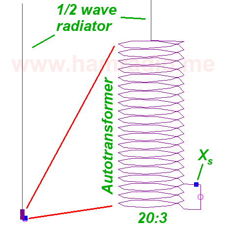
Later I noticed VHF and UHF products with a slightly different configuration using the autotransformer approach. One difference is the VHF+ units typically do not use a ferrite as transformer core while the HF examples do.
EFHW transformer two ways
Let’s review key differences between the HF and VHF+ transformer configurations.
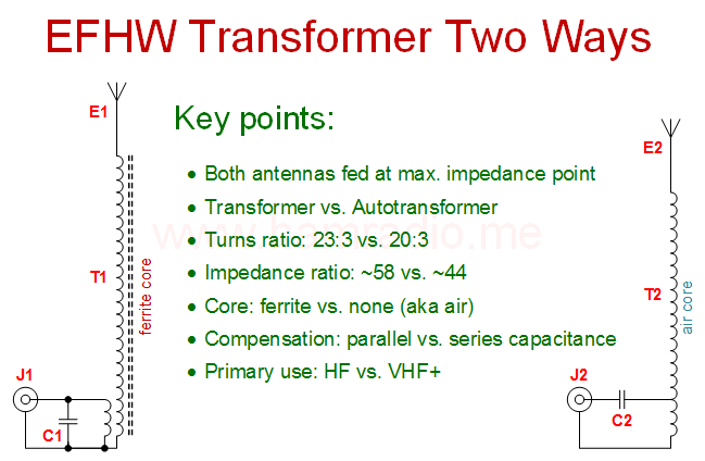
Highlights in figure 2 include:
- E1 and E2 are both aerials with a length such that a current loop (Hi Z) connects to the top of the each transformer. This could be a half-wave aerial or multiple thereof.
- Transformer T1 on the left wraps its windings around a suitable ferrite material usually in toroid form.
- Transformer T2 on the right has no core.
- Shunt capacitor C1 across the low Z side provides reactance compensation for the T1-E1 end-fed system.
- Series capacitor C2 on the low Z side provides reactance compensation for the T2-E2 end-fed system.
- The left schematic represents the actual transformer in the LNR Precision EF-10/20/40 antenna.
- The right schematic represents the autotransformer NEC design I used to simulate and analyze the end-fed antenna concept.
Conclusion
This web site is as much my technical journal as well as article collection. Hence please accept this post as merely a quick reminder the key notion that capacitor position correlates with the core material (or lack thereof).
John, Go look at some old articles on end-fed half-wave and full-wave antennas, like for a half-square. I think you'll find that C1 is not described as "reactive compensation", but part of a parallel-resonant (tank) circuit.
I've seen those and they are indeed prevalent, but they serve to hone in on a particular frequency by tuning C against L. The ones above, especially the HF one, are very broadband suggesting another purpose. Thanks for the comment regardless as it is a good observation.