When I built a copper plumbing pipe j-pole antenna for 2 meters from plans on the internet, I really did not know quite where to put it. I built it at my previous QTH as more of an exercise to teach my son how to solder with a torch.
After testing, years passed.
We moved to a new QTH with lots of room for antennas. However, where to put the J-Pole antenna remained an issue. As a temporary measure I shoved it in a eight foot piece of schedule 40 pipe and lashed it to a fence post. I ran LMR-400 coax and found it works pretty well… at least good enough to finally be net control operator on the local repeaters from the comfort of my shack.
During the Virginia QSO party this year I realized 2 meter mobile operations were very important to support. Vertical polarization was in order and this J-pole was just the thing. I shove the schedule 40 solution into a tree atop a fully extended tree trimming pole. The antenna was pretty sad looking and was still much shorter than our house. It was the best I could do though.
Surprisingly, this antenna worked like a champ and I was able to easily work everyone in our county and any neighbor county with no problem on FM 2 meter.
Time passed.
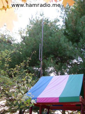
We purchased a cheap Wal-Mart playset for our youngest. After assembly I pondered the obvious… could it host an antenna. The answer is yes and here it is…
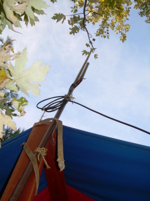
Here is another view showing some details of how the copper j-pole is lashed to the structure of play set using an old dog leash I found in the yard…
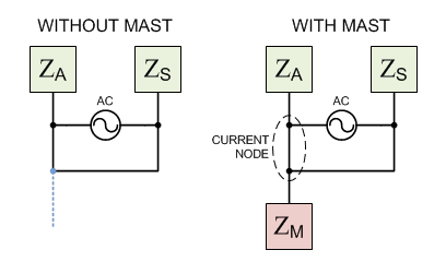
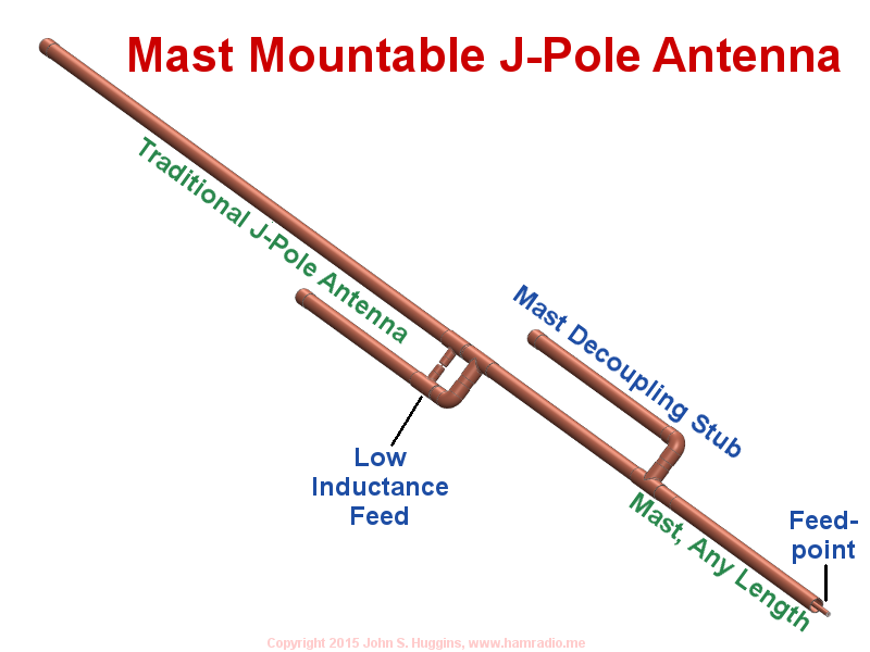
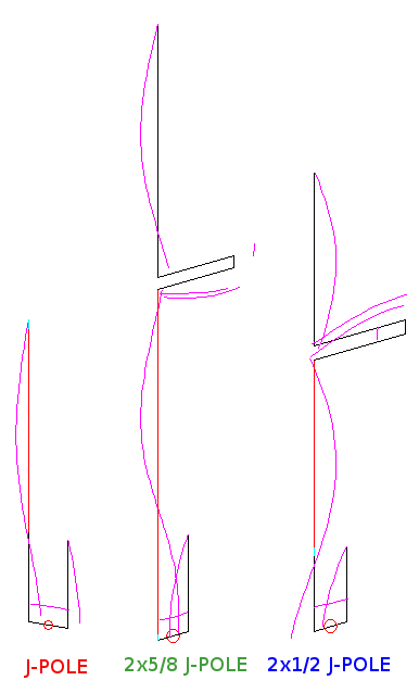
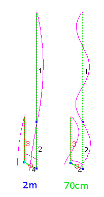
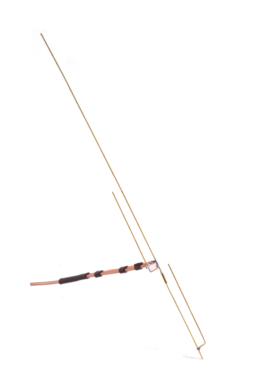
The balun is essential; Its application on this antenna verifies theory and simulation quite well. You will notice the J-Pole has copper pipe extending down to serve as a mount for the rest of the antenna. Ideally only the short vertical (1/4 wave long), the short horizontal portion and the long vertical (1/4 + 1/2 = 3/4 wave long) carry any RF current. The feed point for the RF is a balanced feed quite near the horizontal short at the bottom of the J. You should think of the feed point of a J-Pole antenna as feeding a horizontal dipole 1/2 wave long which is, of course, a balanced feed point. So we have two issues to address concerning feeding of the J-Pole…
- Converting the Un-balanced nature of coaxial cable to balanced
- Ensuring that extra copper pipe beneath the J and the outside of the coaxial cable shield do not conduct RF
I originally tuned the impedance of this antenna by moving the copper straps up and down together until my MFJ antenna analyzer measured about 50 ohms. With this done I just started using the antenna as is. In the shack, the antenna analyzer revealed a natural frequency quite a bit lower than the 2 meter band… something like 140 MHz or so.
If theory was right, the outside of my coax was becoming part of the antenna’s length and, thus, lengthening it. Worse, RF was potentially making its way back into the ham shack.
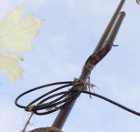
As a quick and dirty test, I coiled up a few loops of the feeder RG58 coax into a coil to create an inductance to un-balanced currents in the coax.
Wow what a difference. This one little change brought the inside the shack natural frequency of this antenna system from 140 MHz to about 145 MHz… spot on.
The SWR measurements for 146 MHz show under 1.5:1; This is very good for the 146.580 MHz FM simplex calling frequency for the Virginia QSO Party.
The SWR measurements for 147 MHz are under 2:1. This is plenty good enough to work my local repeaters.
There are certainly more elegant ways to provide the balun function to this antenna.
Possibilities include:
- Hollow cylindrical ferrite beads along the coax
- Coax wrapped around a large toroid
- An honest to goodness transformer designed around a toroid
That last option offers the antenna designer an option to raise the impedance of the 50 ohm cable to something higher. This, in turn, would move the tap points on the J up the antenna a bit. To keep things simple, a plain ol’ 1:1 choke balun is all we need and is why the coil choke provides a workable solution.
The performance of this two meter half-wave antenna is confirmed. It is a keeper. The only improvement left is to put it on top of my tower… when I get one 😉
You will find plans for the plumber’s special copper pipe j-pole antennas all over the internet. Some of the plans show the 3/4 wavelength section as two pieces: 1/4 wave section coupled to a 1/2 wave section. There is no reason why this should not be one continuous piece of copper pipe 3/4 wavelength long.
Making an antenna out of copper pipe results in an antenna that gets more distinguished with age. Oxidizing copper turns a shade of brown that pretty much serves as perfect camouflage in many environments. You folks in CC&R deed restricted areas can quite likely sneak one of these up in your yard. If a Home Owner Association busy body questions it, just say it is your Asian metallic art piece and provides the yard with good Feng Shui. This is hardly a pink Flamengo or a velvet bust of Elvis (yes I really saw this in a front yard once) so I think you will be fine.
The J-Pole antenna is a unique design that cleverly attaches a tuned feeder to a half-wave radiator. Good luck on yours.
Why wait for green verdigris?
Spray paint the fresh copper on the j-pole with brown, black & tan…you get "urban camoflage" (or move out of those neighborhoods)
Why not clamp your stub J design below the active J so you can eliminate the coil of coax choke?
73' WB4ENE
Could you be a little more specific?