The YouLoop Antenna
The YouLoop small loop antenna is a recent addition to the product line from Airspy. Product details…
The YouLoop is available at an affordable $30-40 US. In a world of +$200 small loop antennas that utilize relatively thick and hearty aluminum or copper tubing, the thin coax that makes up the actual loop appears to be a strategic compromise. Can the YouLoop give satisfactory performance for MF and LF band reception?
Small loop background
The YouLoop’s design derives from a class of electrically small antennas generally called Shielded Loop antennas. Frank Dörenberg (N4SPP) provides an excellent discussion of the small loop as it relates to driving small transmitting loop antennas…
Scroll down to his figures 24A-E to acquaint yourself of the various forms of small “shielded” loops.
Broadband small loop background
The YouLoop uses the crossover Möbius configuration inspired by August Ferdinand Möbius.[1] Both this and the popular “gapped” loop configuration are very broadband in nature as testing results, shown below, confirm. This contrasts with tuned loop LF/MF aerials where a capacitor in parallel with the inductance of a multi-turn loop makes for a very selective, narrow band, and likely more efficient, receive antenna.
This discussion focuses on a single-turn small loop antenna comprised of a hollow conductor arranged in a closed shape, such as a circle, with an insulated conductor within. Two configurations are shown below. Both share a gap in the outer conductor at the top of the loop. Directly opposite this gap is the antenna feedpoint shown here with a broadband transformer serving the role of balanced to unbalanced converter.
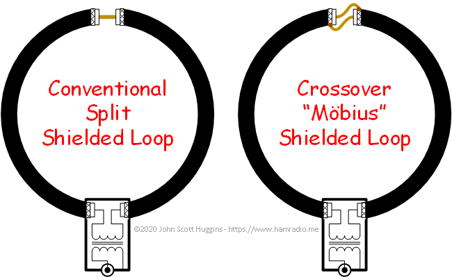
The slight wiring change in the open gap highlights the only difference between the two configurations. The conventional approach merely passes the inner conductor through to the other side. The crossover approach performs an inner to outer swap. Both approaches directly short the antenna feed point at dc.
It doesn’t seem such a simple antenna configuration would provide any usefulness beyond being an inductive feed loop for a larger antenna assembly. The subtle crossover refinements in the Airspy YouLoop beg further review. So let’s do just that.
Definition of Möbius loop (aka Mobius, Moebius)
From Ofer Aluf…
A Moebius loop magnetic field sensor is a circular loop consisting of two solid-shielded 50 ohms coaxial ”arms”, which are split at the top to form a very small gap compared to the loop dimensions. The center conductor of each coaxial arm is connected to the shield of the opposite arm.
Möbius recommended reading
Before going further, add these resources to your reading list.
- Genaille, Richard A. – “V.L.F. Loop Antenna,” January 1963 Electronics World
- Sharp, Everett N4CY – “A Practical Approach to building and Evaluating a Broadband Active Loop Antenna, looking at the Mobius, Conventional Shielded and Wire Loops Everett Sharp N4CY“
- Aluf, Ofer – “Moebius loop antenna system stability analysis under parameters variation“
- Duffy, Owen – “The Mobius strip loop – ham benefits“
Other small loop products include…
- Pixel Loop (now a DX Engineering product),
- Wellbrook Communications – not a Möbius, but a key player in the small loop game.
Airspy apparently felt the need to fill the small loop antenna marketplace with an inexpensive offering.
Introducing the Airspy YouLoop
The moment I learned about the YouLoop and its price point, I ordered one. It arrived as three pieces of intensely blue coaxial cable terminated in male SMA connectors and two small boxes with SMA female connectors. One box has two connectors. The other has three. Two equal length coaxial cables form the symmetrical left and right portions of the actual loop just over 2 feet in diameter. The third serves as a convenient feed line a bit over six feet in length. The figure below gives perspective of this antenna system.

The coax is a stiff variety that holds its shape somewhat. However, when formed into the loop, it will partially collapse under its own weight. I found their choice of coax prudent, but noticed its stiffness can put quite a bit of stress on the connections if things aren’t just right.
All in all it’s a bit underwhelming at first glance, but a close look at the innards of the crossover and feed transformer components reveal delicious grist.
The YouLoop feedpoint with transformer
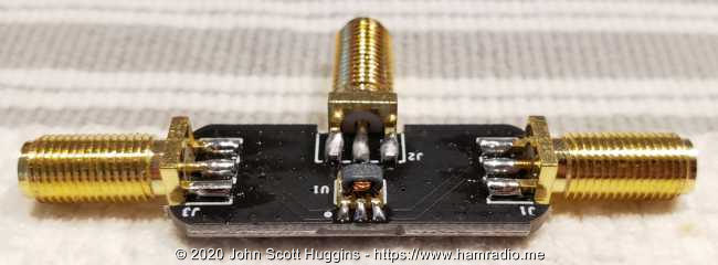
As seen above the middle SMA connector feedpoint connects to one side of the little transformer. The transformer secondary conductors connect to the center pins of the left and right SMA connectors. SMA connector shields are carried through to each other. We all love rf transformers right? Well here you go…

I verified the impedance ratio of the transformer by measuring return loss (50 ohm) by tack soldering various resistors above and below 50 ohms to the secondary side.
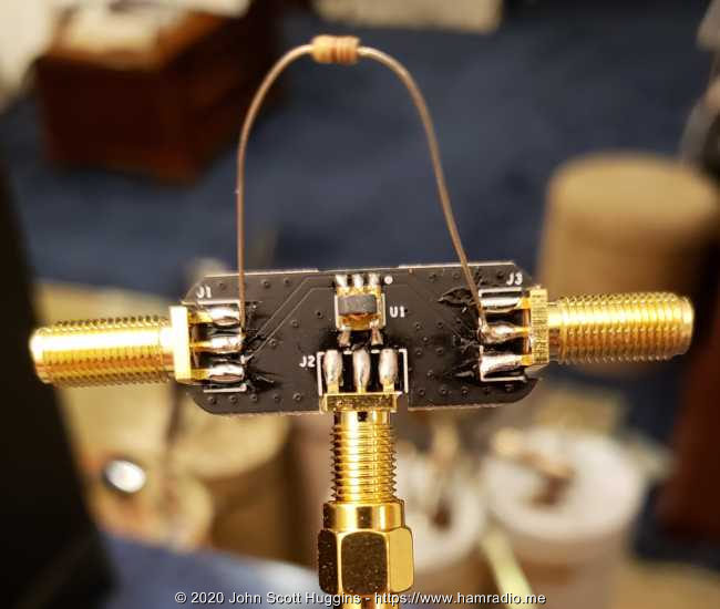
A 47 ohm non-inductive resistor (sorry… didn’t have a 50) produced the best S11 indicating this transformer is 1:1. I was expecting something quite different given the likely ultra low impedance of small antennas.
The YouLoop crossover
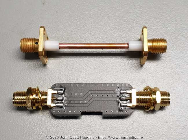
Seen below is the circuit board that performs the YouLoop’s Möbius crossover function.

I’m not sure what to make of the cut-through vias center-bottom, but I guess you do whatever you need to get this initial revision to fit in the provided plastic boxes (not shown)… then to market. Ohmic tests confirm the crossover works per design.
YouLoop antenna test goals
Being an electrically small antenna for LF through HF, the YouLoop and all antennas of similar stature bring with them a concern their feedline might be part of the reason for their success. Hence, the supplied feedline had to go. Add to this the need to ensure no other conductors of any sort are in the vicinity of the antenna system such as power, USB, Ethernet, etc. As well no conductive mast shall be involved.
In short, we need to see if the loop alone can pick up signals reasonably well with just itself and a little receiver at the loop feedpoint.
YouLoop antenna test assembly design
To further the goals outlined above, the six foot feedline was removed and replaced with a set of electronics as shown below.
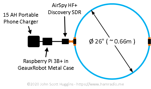
The proportions of the components are roughly correct. From right to left we have…
- The Airspy YouLoop antenna without its feedline, but including the feed transformer and crossover components;
- One SMA-Male to SMA-Male barrel adapter;
- Airspy HF+ Discovery SDR;
- Raspberry Pi 3B+ microcomputer inside housing made of real metal that robustly heat-sinks the board components and doubles as shielding;
- Running on the Raspberry Pi is a boot image from OpenWebRX.
- Not shown is a USB WiFi plugin module to bring the WiFi antenna outside the conductive enclosure;
- Power source is one of those portable USB batteries of immense capacity one uses to charge phones, tablets, and now portable, wireless YouLoop test setups (Thanks to my local Fauquier ARC for this idea);
- One USB cable with ferrite chokes at each end to connect the Airspy SDR to the Raspberry Pi.
- One USB cable with power switch inline to bring power from the battery to the Raspberry Pi.
Everything is off the shelf items. Anyone can replicate this setup with ease. The only issue seen is the occasional low voltage log entry on the R-Pi during high computational moments. If I could jack up the voltage regulator on the USB battery 1/10 of a volt, this wouldn’t happen. It wasn’t a show stopper so I lived with it.
YouLoop antenna test assembly build
Here it is put together on a non-conductive piece of wood. I decided to stack the R-Pi on the battery to shrink the assembly a bit.
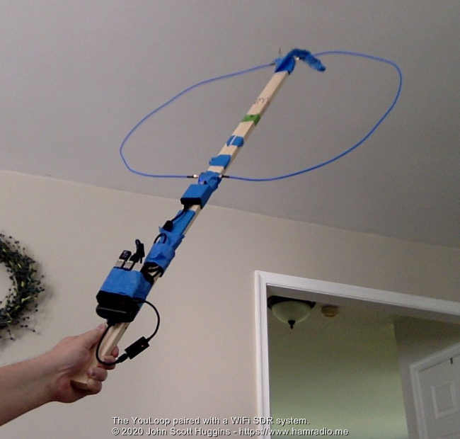
Look ma, no “extra long” wires. No not exactly a Hallmark moment of neatness. One can hope I earned bonus points matching the painter’s tape color with the Airspy coax, but alas, it was mere coincidence.
I had conflicting requirements concerning the distance between the Airspy SDR and the Raspberry Pi. Too short and I risk injecting computer/interface noise into the receiver. Too long and I violate my goal of ensuring only the loop antenna itself is doing the receiving. At the end of the day you just put it together, say your prayers, and start testing. Here are a couple of close-ups…
Yeah the USB cable between the R-Pi and SDR is a bit long. Bundling it up had to do for this test.
After the usual machinations of straightening out network issues, I called up OpenWebRX from the test assembly’s “web site” and immediately was receiving with the YouLoop antenna over my local WiFi. Pretty cool.
I’ve gotta say… performing antenna testing while reclining on a sofa with laptop… so nice. Thanks OpenWebRX!
Indoor YouLoop antenna reception tests
I put the YouLoop antenna assembly on a chair. I quickly noticed plenty of signals. The AM BCB was abundant of course, but also our local Culpeper NDB… and to my surprise WWVB. Loops are famous for their azimuth nulls so nulling the local NDB beacon was my first test.
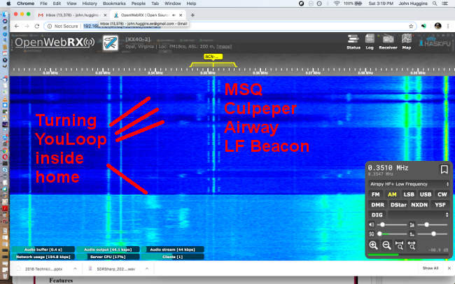
I didn’t think this would be possible inside a home with myriad conductors about, but indeed it was quite apparent I could significantly null the NDB beacon along with other signals by turning the loop in my hand. I wasn’t expecting much of anything like this from my basement.
More basement tests from K2PI
Robert Harvey (K2PI) ran his spotter system with his new Airspy YouLoop affixed to his basement wall inside his home. These 20m and 40m spot reports confirm good HF performance from the YouLoop.

Similar success occurred on 80m including a ZL midday spot.
Outdoor YouLoop antenna reception tests
It was time to take the YouLoop test assembly to the great outdoors for some field testing. I fastened the assembly to my portable speaker stand.
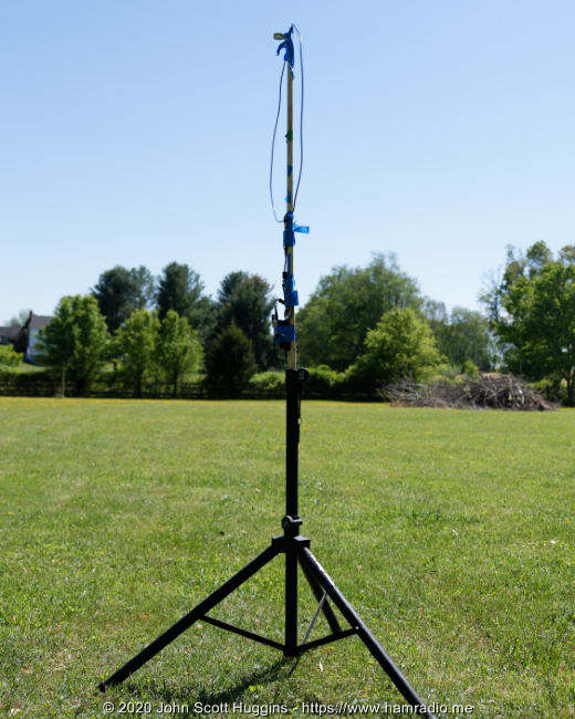
Yeah the speaker stand is made from conductive aluminum so there is some concern of it being in the near field, but you do what you have to do. I also did tests with the wooden assembly lashed to an eight foot fiberglass mast to put more distance from the stand and between the loop and earth.
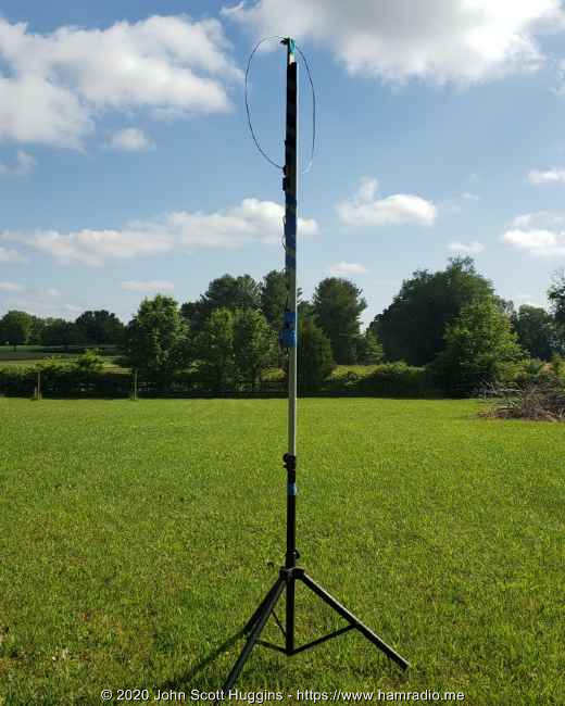
This puts about two feet between the speaker stand and the R-Pi/Battery stack. It is what it is.
Receiving results
Results are, in short, pretty darn impressive. The electrically small un-tuned loop antenna paired with the HF+ SDR at its feedpoint simply works.
- I can hear WWVB in the day and evenings from inside or out.
- The 351 kHz beacon about 13 miles south comes in loud and clear… via ground wave no doubt.
- AM broadcast stations come in day and night.
- OpenWebRX provides ample FT4/8 reports on HF.
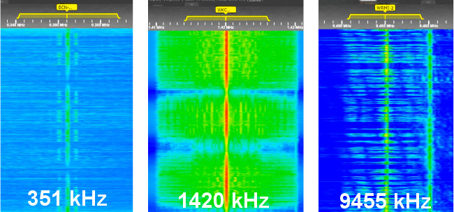
I recorded three different OpenWebRX waterfalls while listening to three strong daytime signals: The Culpeper aviation beacon to my south, a local AM broadcast station to my north and a distant HF shortwave broadcast station. Each time I rotated the loop antenna in azimuth once to check for nulls. The three results are combined below.
Key takeaways…
- 25 watt 351 kHz beacon about 13 miles (22 km) south – The nulls are deep, crisp and narrow;
- 22,000 watts – 1420 kHz WKCW about 7 miles (11 km) north – Very strong. No surprise. The nulls are deep, crisp and narrow.
- 9455 kHz – I don’t recall which station this is, but it was reasonably easy to hear. Any nulling was imperceptible. Tilting the loop didn’t help… or hurt.
The YouLoop has good pattern shape with deep nulls best observed during reception of lower frequency ground wave signals. This works for WWVB as well. Nulls are much less apparent at higher frequencies and/or skywave propagation.
Möbius vs conventional split loop
A discussion of the Airspy YouLoop antenna design is incomplete without comparing the crossover with simpler approaches. Does the crossover really provide any measurement benefit? The modular nature of the YouLoop with its SMA connectors makes for an easy test by replacing the crossover with a similar length straight through equivalent as shown below.
There are numerous discussions theorizing this question. Many firmly focus on noise performance. For all except WWVB, I could discern little difference in noise levels as there is too much energy in my setting to make any sense of a noise floor. However, the signal strength of the primary carrier of various AM signals are strong, stable and easy to measure with OpenWebRX.
The Airspy HF+ Discovery as test instrument
Taking a tip from Owen Duffy, I tuned AM carriers to the middle of a USB pass band to ensure the signal of interest is comfortably within a demodulation window. This works very well.
I checked the gain and linearity of the Airspy SDR at various frequencies against a reference generator. With the 10 dB preamp turned on, I found gains from 7 to 13 dB depending on frequency. However, for any given frequency, the relative accuracy across large swings in power was well within 0.3 dB. This proved more than sufficient for the referential measurements below.
Test signal candidates
Test method and gear thus fleshed out, I put together a list of local daytime AM broadcast stations with nice steady signals within 50 miles. All are to the north and east. To this I added western WWVB and the southern Culpeper 351 kHz beacon. I also listened to the northern Canadian CHU time signal on 3330 kHz.
The chosen YouLoop azimuth avoided a null on any stations of interest. The azimuth for each measurement session was precisely the same.
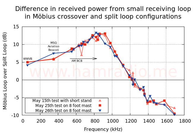
I ran the test in three sessions, calculating the difference in dB between Möbius crossover and split loop configurations. Keeping in mind the 10 dB preamp, measured power levels range from -116 dBm (WWVB) to -48 dBm (WKCW). Being a comparative test, I subtracted the split loop readings from the Möbius crossover readings resulting in the easy to plot signal strength difference.
The 3330 kHz CHU time signal was strong in all tests, but signal strength varied too much with propagation to be a good measurement reference. Hence it is excluded from the results below.
Key takeaways
- All three sessions overlay quite nicely.
- The Möbius crossover configuration provides a significant improvement in received power over the non-crossover up till about 1100 kHz.
- Both approaches offer similar performance between 1100 and 1300 kHz.
- The non-crossover configuration bests the Möbius crossover above 1300 kHz.
- Regardless of these differences, both exhibit excellent broadband performance.
While this difference is interesting and useful to understand, it’s satisfying to know both configurations provide yeoman’s service to the radio enthusiast. That said, it seems the crossover approach may well be superior for 1MHz and down.
What about noise?
As hinted above, WWVB was the one place where I saw a difference in the noise floor identical to the 5 dB difference noted in the above data. Both the WWVB signal and the noise floor just next to it moved identically with the change of antenna configuration. Here are the Airspy’s measured power values…
- WWVB with crossover: Signal -111 dBm, Noise -116 dBm
- WWVB with straight: Signal -116 dBm, Noise -121 dBm
Here are measured power values for the 351 kHz beacon…
- MSQ Beacon with crossover: Signal -93.9 dBm, Noise -125 dBm
- MSQ Beacon with straight: Signal -99.8 dBm, Noise -125 dBm
Perhaps something can be said about the effect on noise concerning WWVB, but not sure what to say about the MSQ beacon. It’s also quite possible the Airspy receiver is performing some signal processing to mitigate noise for the listeners benefit. That would, of course, spoil any noise measurement efforts.
Long story short, I don’t have any practical conclusions to give concerning noise performance of this loop antenna.
Conclusion
The lack of final judgement about noise performance aside, the other measurements reveal a solid trend one can use to understand their choices. The YouLoop holds its own on receive performance in a small, thin package.
Airspy YouLoop advantages:
- Stunningly simple and straightforward electrical design.
- Hey it works. It’s an electrically small, no fuss, antenna.
- Functions perfectly fine with no counterpoise or equivalent connection to earth.
- It doesn’t require power although a decent feedpoint receiver or pre-amp will probably not hurt.
- Broadband by nature requiring no tuning components.
- Quite inexpensive. Superb price point.
- Works shockingly well indoors… ¯\_(“)_/¯
- This thin antenna can be legitimately fastened to the back of wood furnishings, artwork, etc. to become a hidden low band receive antenna.
Airspy YouLoop disadvantages:
- The loop doesn’t mechanically support itself like some of the $200+ competitors.
- The relatively stiff coaxial cable isn’t quite rigid enough to hold a loop shape on its own.
- A LOT of weight and twist strain exists on those SMA connectors and the PCB that holds them.
- The novel SMA PCB top and bottom components appear to be stress points if the coaxial cables are not carefully arranged and fastened. The plastic housing certainly helps, but care is advised.
Considerations for any small loop antenna:
- Ferrous materials should probably be kept well away.
- As there is no escaping Chu-Wheeler limits, these antennas are very inefficient.
- Thankfully inefficiency isn’t a show stopper for receiving purposes on the low bands.
In summary, Airspy has a winner with this product. It brings the advantages and capabilities of a well designed small loop antenna to a broader audience thanks to the new price point. It isn’t mechanically as tough as it’s more expensive contemporaries. Then again it’s not tough on the wallet either. The apparent good performance inside a building makes this a possible choice for HOA bound or retirement community radio listening enthusiasts.
So long as you handle the YouLoop with care, it is an exceptional value to the low band receive enthusiast.
References
- https://en.wikipedia.org/wiki/August_Ferdinand_M%C3%B6bius


Thank you very much for performing this test. Your efforts, experiment and results are extremely appreciated ! As you are probably aware, the Mobius loop has been the subject of much theoretical debate for decades for LW through SW use. A couple decades ago, I performed a similar series of tests using a simple loop, split shield loop and Mobius loop with classic small loop inductive interface and found no significant difference except for an apparent/possible resonance shifting presumably due to distributed capacitance of the coax shield. At the time SDRs were not in existence so my 'instrumentation' was limited to a 1 uv receiver sensitivity. COMMENT: It would be very instructive if you could repeat the test using a non-shielded 'simple loop' in comparison to either the split shield or Mobius loop. Best regards. Bill.
I agree with Bill. I have read in a couple places that the balun is absolutely critital for this antenna's performance, doing both choking duty on all bands but also some impedance matching in places (forget where, sorry) making it more broad-banded in think?
Since the ferrite material may be a tipping point, did you have a chance to check the BALUN frequency response and loss (0.28 dB loss typ)? I doubt that the small ferrite core really behaves well between the stated frequency range 10kHz to 30 MHz.
So far I did not find anyone who uses compared of performance of Möbius based receive loop antennas, with the round long Ferrite rods from stand alone AM radios or the the smaller flat Ferrite Rods in portable AM radios. These ferrites were optimized for MF. Do you have one of those ferrite roads and time to please compare it to the Möbius Loop antenna?? Joachim
The YouLoop was first discussed in the airspy groups.io group in 2017, long before it became available commercially. I used 75 ohm RG59-Mini co-ax to construct mine and used a BN73-202 binocular core for the matching transformer. The original design used the smaller BN73-302 core with 5 turns per winding, so the commercial product probably uses something similar. I have two YouLoops, both inside our home. One is 5 feet by 3 feet and is around a window frame, hidden by the curtains. The other is in my roof-space and is of similar size to the commercial product. The large one assumes a rectangular shape when in use, while the one in the roof-space looks like an inverted triangle when suspended from the rafters. Both work well from LF ( I have received SAQ on 17.2kHz) to over 20 MHz and surprisingly well on the FM band and at around 215MHz, which is used for digital radio in the UK. For the 215MHz transmissions, which are vertically-polarised, the YouLoop functions better with the feed-point and crossover in the vertical sides of the rectangle. I can't adjust the one in the roof, but it works quite well as it is. Here in Southern England, the small one in the roof is capable of receiving US East Coast MW stations on my Airspy HF+, if conditions are right, although I do use a 30dB (adjustable) LNA as a feed of 16-metres of RG59-Mini has too much loss for the low- level signals from the YouLoop. I found that 12dB gain was sufficient on MW. The main advantages are good signal-to-noise performance, cheapness, easy construction, good performance indoors and useful from LF to VHF.
Very interresting paper. I've ordered one to play with.
In the link https://www.researchgate.net/publication/32235109…
I've read something that sounds like a conclusion to me : " The important electrical characteristics of the Moebius strip
loop are, therefore, its doubled sensitivity, and its quartered
frequency response. "
OK, I know I'm late to the party, but I just found the article…
One thing I've found using loop antennas indoors on 80m is that there often is very strong coupling between the loop and the electrical wiring. As a result, the position of the loop to null a signal had no relationship to the actual direction to the transmitter, but instead was alligned to the wiring in the ceiling and walls. When the loop was at right angles to the nearest wiring, the signal was minimum.
So you might want to test that with an indoor loop: the capture area may be larger than the loop by itself.
– Dale WB6BYU