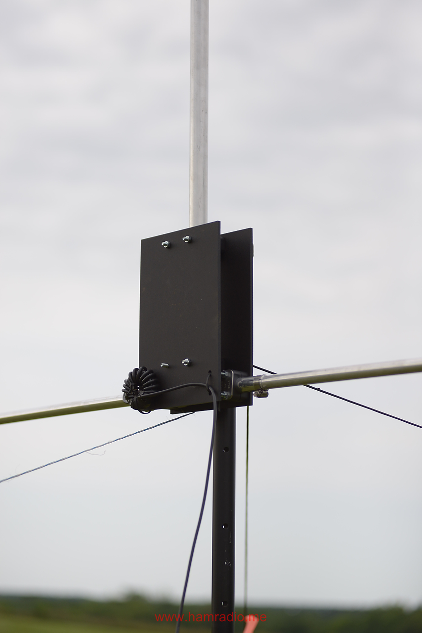
6m Vertical Dipole Antenna
There are many ways to achieve 6m radio operation with straightforward antenna designs. If, however, you were wondering if the aluminum already in the 20-10m AHVD design might hit 6m, read on to see if it will become a 6m vertical dipole antenna.
Why Six Meters
It seems just about every rig these days includes the 6m band in its available frequency range. This includes my portable Elecraft KX3. It’s almost as if the “Magic Band” is lumped in with HF these days.
While developing my portable version of the Asymmetrical Hatted Vertical Dipole (AHVD), I did not concern myself with 6m. After all, how hard is it to carry a 6m dipole?
As seen in previous articles, my current AHVD prototype tunes 20-10m with ease yielding an antenna an electrical halfwave in length – vertical height plus radial spoke length. Note, the physical length is different than the electrical length as discussed in the primer AHVD article. Could the elements be shortened further to hit 50 MHz?
Simulations say yes
Off to NEC I went to search for element lengths within the clamp range. I found not one, but three 50 ohm points.
- First is the typical “looks almost like a quarter wave ground plane” antenna. This is just like the 20-10m configurations, but smaller. I will call this ‘Normal’ in this article.
- Because of the long length available in the vertical aluminum, a second 50 ohm point occurs where the entire antenna is a full wave in electrical length. I will call this “Tall” in this article.
- A third configuration greatly lengthens the radials leaving a short vertical. This is also a full wave in electrical length. The simulations show the azimuth pattern is not as round as the others. It’s not bad, but I didn’t pursue this configuration further.
Figure 1 shows the first two topologies highlighting respective size along with current intensity and phase.
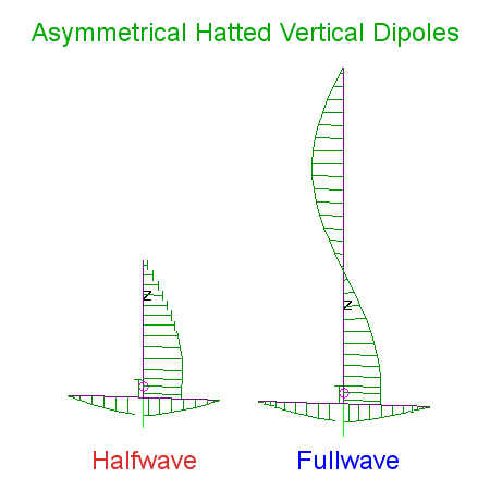
The fullwave configuration should strike fear into antenna aficionados. The opposing phases on the vertical portion do mess with the pattern in ways we likely don’t want.
Figures 2 and 3 show the elevation and azimuth patterns of both antennas.
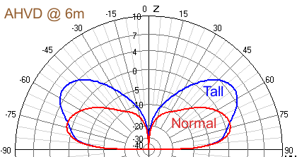
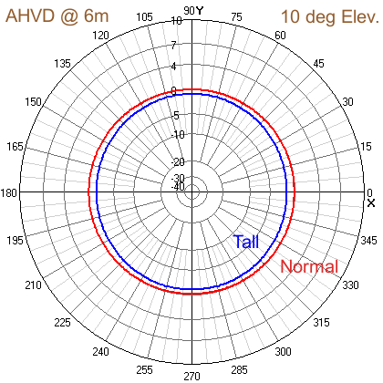
Simulation suggests the taller antenna isn’t helping low-angle signal launching despite the surprising boost seen at higher angles. It is interesting enough to try though.
Real Tests of the AHVD on 6m
With simulation dimensions in hand, I grabbed the baseball bag containing the 20-10m AHVD, my VNA, my KX3 and headed out the door.
Normal “Halfwave” Version
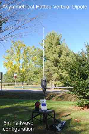
The first test was to make the “Normal” version of the AHVD. I ultimately had to remove all, but the inner 3 foot pieces from the horizontal bar to get close to 50 ohms. After some back and forth, the best length of each vertical section came out to 5.5 inches which equals 74.5 inches total vertical length.
Figure 4 shows the result…
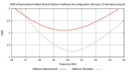
Figure 5 shows the measured and simulated SWR of the shorty 6m AHVD.
This isn’t what I was hoping for. The trend I saw suggests shorter radials will get us to 50 ohms. If I create a custom design just for 6m, this is no problem. However, my goal here is to see if the aluminum presently in the 20-10m can reasonably reach 6m. The above test shows promise. The antenna is useable with a matcher.
Tall “Fullwave” Version
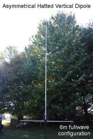
Next I lengthened the vertical section searching for a good match. Once again, the best results require the removal of the extra aluminum from the radials leaving only the two 36 inch pieces. Figure 5 shows the result when the vertical section lengths are set to 23 inches each for a total height of 197 inches.
Figure 6 shows this result…
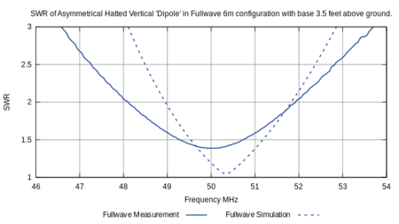
Figure 7 shows the measured and simulated SWR of the tall 6m AHVD.
This is more like it. Note both simulations and measurements suggest a narrower bandwidth than the shorter method, but it still has ample range like the 20-10m configurations. Just like 20 through 10m, the AHVD is forgiving.
On Air Tests
I gave a shout out on the local repeater and the club email reflector to round up some folks to 50.167 MHz. In short order, I had three folks willing to help me test things out.
Figure 8 shows the “portable” operation using the taller antenna approach.
My first attempts were not producing results. Then I checked the power setting. It was set to 1 watt. I set it to 10 watts and, viola, no problems communicating on 6m to the local folks.
Local contacts are not really much of a test, but at least it confirms something works. I began to wonder if the taller configuration provides some benefits. I didn’t have time to test the two antenna configurations in subjective A/B tests, so I packed things up. Later I pondered the situation.
Is the Fullwave AHVD pattern really a problem?
As figures 1 and 2 reveal, having opposite currents on the primary radiating element moves the energy into various directions. This is a far field summing phenomena. What if the bottom third of the antenna was blocked by nearby objects as theorized in Figure 9…
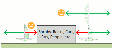
This presents a scenario where the top part of the antenna may actually help get your signal over obstructions.
I simulated a vertical 6m half-wave dipole with the top coincident with the top of the tall AHVD configuration. Figures 10 and 11 compare the resulting pattern with the previous antennas…
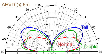
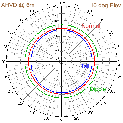
If my theory is true, the 6m tall configuration of the AHVD antenna may help “peer” over local obstructions and squeeze a little more energy towards the horizon.
Conclusion
The above tests and simulations suggest the Asymmetrical Hatted Vertical Dipole design for 20-10m can, with some radial aluminum removal, reach 6m. The “tall” version gets a significant halfwave of current nice and high albeit with some far field interaction from the lower opposite current.
The RG316 balun seemed to choke well enough for QRP, although hand tests suggest it’s not as capable at 6m.
Despite the above realities I think it is safe to say the 20-10m AHVD antenna can function at 6m and provide the operator with a freestanding 6m antenna solution with little fuss.
