LFA Yagi Antenna
This post highlights some of the technical and intellectual property points concerning the Loop Fed Array (LFA) high performance Yagi-Uda antenna designs created by Justin Johnson (G0KSC)[1] and his computer technique using NEC and self-refining Particle Swarm Optimization and other Genetic Algorithm techniques.
This is very similar to the technique used by OTA DTV enthusiasts using NEC and a statistic reducing program to refine the original Hoverman TV antenna to its modern superior performance for DTV reception. The result for the DTV crowd is a superior redo of a functional older design providing wide bandwidth and good gain.
The result from Justin is a superior redo of folded dipole Yagi-Uda designs. His numerous simulations provide a panoply of practical, plus a few concept antennas, for us to consider adding to our DX weapons in our amateur radio pursuits.
A more appropriate name for this new Yagi-Uda arrangement is Coplanar Loop Fed Array (CLFA) since the full-wave loop is laid flat in the array along with the parasitic elements.
Simulation Empowers
Reading the comments in this thread reveals why almost any ham can, using NEC2 or NEC4, derive useful, even superior, antenna designs without an antenna engineering background. The use of Particle Swarm techniques with NEC is a productive way to increase the odds of stumbling into cool new designs.
The Coplanar Loop
Lo-Z
Since Yagi-Uda antennas tend to lower the input impedance of the feedpoint due to the shunting effect of parasitic mutual coupling, antenna designers have sought ways to raise the impedance to match commonly available transmission lines. Various matching techniques exist including the gamma match, T match, step-up transformers, etc.
The Folded Dipole – Nature’s Perfect Yagi-Uda Driven Element
The folded dipole, with its naturally higher-than-a-dipole feed impedance, will also tend to lower its impedance when placed within the induction fields [11] of the other Yagi-Uda parasitic elements. This technique isn’t really an impedance matching technique since no impedance conversion occurs in operation. Rather it is a sort of all-natural way to achieve a 50 ohm balanced feedpoint using only conductors in the right proportions. It is no surprise the records suggest the handy folded dipole has been in use as a driver element in both orthogonal and coplanar Yagi-Uda antennas since at least WWII.
The Fatter Folded Dipole
Justin’s simulation results use a folded dipole “loop” planer to the array. I suppose he calls it a loop since his simulation results reveal longer loop sides with shorter loop widths work well. At the end of the day, the LFA is a Yagi-Uda antenna with a full-wave folded-dipole loop, with wider sides, within the induction field [11] of the entire array.
This brings me to my favorite characteristic of full-wave loops… natural balance at the feedpoint.
Full Wave Loop Natural Balance
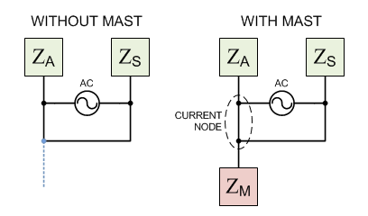
The LFA offers one more very important characteristic… a naturally balancing antenna feedpoint. It’s true. Full-wave loops are quite capable of performing the role of balun simply by the nature of the loop. Read “The Folded Dipole: A Self-Balancing Antenna” by Buxton, Stutzman, Nealy and Orndorff [2] for initiation into this topic. Knowledge of the self-balancing nature of full-wave folded dipoles dates back to at least 1961 [12][13]. C. T. Tai discusses the attributes of the Folded Dipole introducing the “superposition of two models” concept to a greater audience.[17] One result from this discussion is this equivalent circuit where a transformer highlights the tendency to suppress feedline currents…
To verify this self-balancing capability, I used NEC models of my LFA and NBS 3 element antennas with various wire lengths hanging from one side of the feed-point. My goal was to present low impedances to the feed-point to try and draw current on the new wire. Do this to a dipole and significant currents will flow on the new wire and greatly disturb the pattern. However, the loop feed strongly resists current flow on the new wire. Figure 1 shows my simulation of a standard NBS and LFA Yagi-Uda with a worst-case 1/4 wave wire connected to one side of the feedpoint. The new wire presents a low impedance to the feed and will compete for current and try to spoil the pattern… much like a mast spoils a j-pole’s pattern.
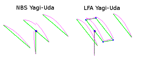
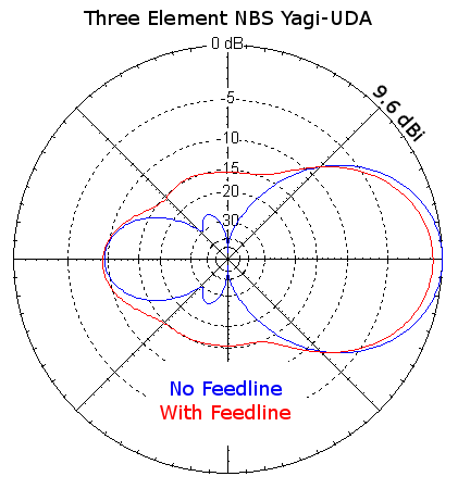
The new wire simulates the effect of RF flowing down the feedline shield. The wire draws about 26% of the current from one of the dipoles resulting in the before and after plots in figure 2.
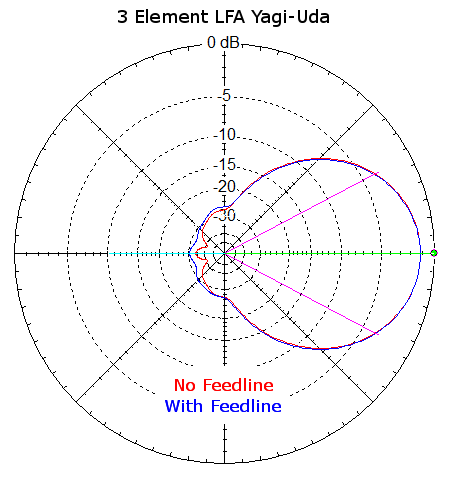
In the LFA, the extra wire draws about 4% of the current from the self-balancing loop resulting in the before and after plots in figure 3.
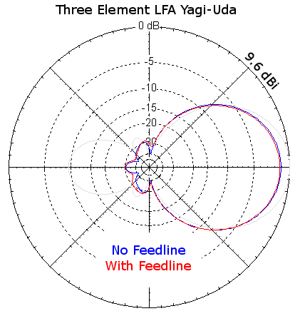
Figures 2 and 3 normalize the outer gain circle to the NBS Yagi-Uda peak gain. The LFA trades a bit of gain for much smoother f/b. However, the important point is how well the LFA holds up to impedances presented by feedlines.
I don’t know if Justin realizes the self-balancing advantage of his design. His discussion of “Creating a balun” on his web site indeed highlights how a dipole can be thrown off balance by an extra wire. However, he misses the opportunity to simulate his loop under the same conditions where the self-balancing nature becomes immediately apparent. Instead he delves into alternative approaches including the Folded Balun (aka Pawsey Stub) while completely missing the fact these stubs form a parallel transmission line with external fields easily perturbed by surrounding conductors and dielectrics.
What he lacks in understanding of antenna feed systems he more than makes up for in this superior new Yagi-Uda antenna design.
The good news for us is we can simply attach the coax directly to the feedpoint with no balun and get good results. Low noise purists will still use a balun to try and get that 4% down to nothing. It likely can’t hurt… unless, of course, you stuff a Pawsey stub inside an aluminum boom.
[UPDATE Fall 2012]
Hand-tests on other antenna designs often reveal horrific feedline currents. Hand-on-the-coax VNA tests performed on my 3 Element 6m LFA confirm the balanced nature of full-wave-loop as used at Field Day with aluminum boom and mast. Try as I might, I could not see any effect on the S11 while perturbing the feedline with my hands and other conductive objects.
Justin’s comments to me via email and others’ observations suggest while the full wave loop tames the induction of currents in the feedline (as shown in simulations and my hand test), they are still not zero; Therefore, the addition of some sort of balun or choke arrangement should allow the operator to obtain the very best low noise performance from their LFA.
The point to take away from this “Natural Balance” section is while the balun fed LFA is the very best way to go, the feed with no physical balun still has a mechanism in place, via the full wave loop, to quell most of the current… as discussed, prototyped, measured and verified by C. G. Buxton, et. al.[2]
[/UPDATE]
LFA Copyrights and Patents
With any worthwhile design comes greed, avarice and lust from every quarter.
Copyright doesn’t protect ideas
Justin tries to copyright his designs on his web site with this erroneous phrase…
…while completely missing the fact that, at least in the US, copyrights do not protect designs. A patent is the correct tool to protect a design. Britain has the same approach. Smartly, Justin is moving forward with a patent application to protect his corporate licensees since without it there is no intellectual property to license.
Prior art – Photo
The flat loop concept may be Prior Art as the flat full-wave loop design may have been with us since WWII[3]. Justin refutes this claim (web page removed by Justin sometime during Autumn 2012) using a, believe it or not, Photoshop defense.
You can’t make this stuff up folks. Clearly this potential Prior Art has touched a nerve.
Prior art – Antenna Engineering Handbook
The 1st edition of the Antenna Engineering Handbook [17] reveals 1961 knowledge of the folded dipole in the Yagi-Uda topology…
The 2nd edition of the Antenna Engineering Handbook [10] shows the Loop Fed Array Yagi-Uda in figure 4.
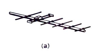
It is clear this drawing is merely an illustration of a six element Yagi-Uda array. It is used repeatedly elsewhere in the b, c, d, etc. parts of the larger figure showcasing how to arrange multiple antennas to form arrays. Nonetheless, it is interesting what the authors chose as their “illustrative” driven element for their example beam antenna.
Prior art – Hand Held Rectangular Loop with Reflector
Here is a unique approach towards an HT satellite antenna called, the CJU Antenna, using a flat loop with one reflector in a PDF file allegedly published in Unión de Radioaficionados Españoles magazine in June 2006. The earliest mention I found was May 2006 in the Amsat.org list. The video is long gone, but here is a Youtuber demonstrating his LFA in February 2009…
Prior art? – Commercial examples of flat loops in arrays
Many companies make coplanar loop fed Yagi-Uda antennas[4][5][6]. However, it is unclear when the manufacturers initially produced their LFA models.
Prior art – Patents
The US Patent office has a few antenna designs using flat loops as feeds for Yagi-Uda antennas. None of them address the attributes of Justin’s focus and some of them are quite bizarre in their claims.
Relevant patents include:
- US Patent 2,452,073 – Folded Dipole – 1948
- US Patent 2,465,673 – Antenna [with coax fed planar folded dipole, reflector and director] – 1949
- US Patent 7,286,097 – Yagi Antenna with Balancing Tab – 2007
- US Patent 8,022,887 – Planar Antenna – 2006/2011
Prior Art – Yagi himself
A picture of, allegedly, Yagi himself holding a Yagi-Uda antenna with a full-wave folded dipole loop as driven element appears on Antenna-Theory.com. [14] This dates the coplanar loop fed array concept to 1976, the year of Yagi’s death, or before. [15]
The process of finding antenna solutions is Prior Art!?!
An interesting find while researching the patents was this one defining the actual process of iterating, guiding and refining simulation results to hone in on a usable antenna design…
The above targets a specific antenna topology as the goal of the simulation process. I forgot processes can have patents. Perhaps Justin might considering patenting his technique.
Prior art – Scholarly and Professional Papers
I am continuing the search in the regular antenna engineering publications. So far, nothing, aside from techniques parallel to the patents above, has been found, but the search has not been exhaustive. There are several references to computation techniques, however. [7][8][9]
Prior Art Summary
Clearly there are many references to the LFA concept in the literature. Whether a traditional narrow folded dipole or more rectangular loop, the full-wave circumference driver has been a part of Yagi-Uda designs since WWII.
According to the commercial LFA site [16] the LFA has:
- “a rectangular shaped, full wave loop driven element” (Prior Art),
- “that is laid flat on the boom between and in-line with the parasitic elements” (The descriptive word is coplanar and is Prior Art)
- “The smaller end sections which run parallel to the boom, are engineered to be 180 degrees out-of-phase with each other” (An obvious result in any rectangular full-wave loop);
- “[. . .] each side cancels the other out and therefore, minimum radiation occurs [. . .] [suppressing] side-lobes [and] improving F/B and F/R ratios.” (likely patentable)
Many individual attributes of the LFA Yagi concept have been around for many years. However, the gathering of these attributes to yield one particular assembly is certainly patentable. I’m eager to read the novel improvements in Justin’s patent claims.
Generous Terms for Hams
Regardless what happens the good news for hams is Justin, when and if the PTO awards a patent, will provide generous terms for free use of his designs to Amateur Radio. Plus if we are honest, we have him to thank for bringing this technique back into the limelight regardless the outcome.
References
- Johnson, Justin (2009-2012). G0KSC – High Performance Antennas.
- Buxton, Carey G., Warren L. Stutzman, Randall R. Nealy and Aaron M. Orndorff (2001). The folded dipole: A self-balancing antenna. Download.
- LuftArchiv (c. 1940s). Photos of German Luftwaffe airborne radar antennas including one with the LFA style.
- “Yagi Antenna Model AD-40/2-3” – Slovenian company with several antenna products using the flat loop feed.
- “Renair Antennae” – British company with serveral antenna products using the flat loop feed.
- “VHF YAGI TV Antenna (5E-512)” – TV Antenna with Flat Loop Driver.
- Jones, E. A. and W. T. Joines (1997 September). Design of Yagi-Uda antennas using genetic algorithms, (Vol. 45, No. 9, pp. 1386-1392). IEEE Trans. Antennas Propag.
- Venkatarayalu, N. V. and T. Ray (2004 July). Optimum design of Yagi-Uda antennas using computational intelligence,. (Vol. 52, No. 7, pp. 1811-1818). IEEE Trans. Antennas Propag.
- Kuwahra, Y. (2005 June). Multi objective optimization of Yagi-Uda antenna (Vol 53, No. 6, pp. 1984-1992). IEEE Trans. Antennas Propag.
- Johnson, Richard C. and Henry Jasik (1961-1984). Antenna Engineering Handbook
. (2nd ed., pp. 27-7). New York: McGraw-Hill.
- Griffith, B. Whitfield (1962). Radio-Electronic Transmission Fundamentals
. (p 323). New York, Toronto, London: McGraw-Hill.
- Hayashida, Shogo, Hisashi Morishita and Kyohei Fujimoto (2002). Self-balanced and wideband folded loop antenna for handsets.
- Uchida, H. and Y. Mushiake (1961). VHF Antenna. Corona Publishing CO,. LTD, Japan.
- Bevelacqua, Peter Joseph (2012). “Yagi-Uda Antenna.” Antenna-Theory.com.
- Wikipedia contributors. “Hidetsugu Yagi.” Wikipedia, The Free Encyclopedia. Wikipedia, The Free Encyclopedia, 27 May. 2012. Web. 5 Sep. 2012.
- Johnson, Justin (2009-2012). InnovAntennas.
- Tai, C. T. “Characteristics of Linear Antenna Elements.” Antenna Engineering Handbook. Ed. Henry Jasik. New York: McGraw-Hill, 1961. 1st ed., pp. 3-13 to 3-15. Print.
![Folded Dipole Equiv. Circuit [17]](http://www.hamradio.me/wp-content/uploads/2012/08/FoldedDipoleDqivCircuit.png)
![Planar Folded Dipole Yagi c 1961 [17]](http://www.hamradio.me/wp-content/uploads/2012/08/FoldedDipoleInYagi1961.png)

I have used it fr several years.