Antenna Gain Definition
Paraphrasing from my college EM book…
“The directive gain Gd(theta,phi) of an antenna pattern is the ratio of the radiation intensity in the direction (theta, phi) to the average radiation intensity and is usually denoted by D = Umax/Uav = 4piUmax/Wr (Dimensionless). Directivity is frequently expressed in decibels, referring to unity. [. . .] Obviously, the directive gain of an isotropic or omnidirectional antenna (an antenna that radiates uniformly in all directions) is unity. However, an isotropic antenna does not exist in practice.”[1]
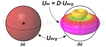
If we compare the average radiation intensity Uavg of an isotropic to a real antenna (in this example a Diamond CP22E 2m omni), we obtain figure 1 where Directivity (D) expresses how the real antenna robs power in some directions (indicated by green, yellow and orange colors) and “directs” it towards the horizon (red and purple colors). Part (a) shows radiation intensity distributed isotropically and (b) shows radiation intensity of the Diamond antenna. The result is maximum radiation intensity Um around the waistline of the antenna where Um = Directivity x Uavg.
Gain vs. Directivity
Open any college text book on antenna design and within the first 50 pages you will learn that Directivity (Directive gain) of the antenna assumes no losses in the antenna structure. The texts agree the term Gain does take into account antenna efficiency and is simply the Directivity times the efficiency factor. Most amateur radio antennas are very efficient making Directivity and Gain practically identical.
Notable exceptions to antenna efficiency are amateur antennas for receive only where lossy elements such as resistances along with conductor layout create a desirable pattern, but with poor efficiency. Here a graph of Directivity and Gain will share the same pattern shape, but with differing amplitudes. The poor efficiency by design takes into account some HF amateur bands are very noisy leaving little advantage for an efficient receive antenna.
Isotropic?
If no real antenna yields a pattern with an isotropic shape, what good is isotropic antenna reference you say?

The answer is mostly because of all the possible antenna gain references one can surmise, only the isotropic has a truly fixed value… by definition. The isotropic radiator has become the de facto standard gain reference throughout the antenna kingdom. Stutzman and Thiele comment…
“Frequently gain is used to describe the performance of the antenna relative to some standard reference antenna. In that case maximum power gain is defined as the ratio of the maximum radiation intensity from the antenna Um to the maximum radiation intensity from a reference antenna Umref with the same input power, or… Gref = Um/Umref. This is a convenient definition from a measurement standpoint. The previous definition of gain employs a lossless isotropic antenna as a reference antenna. This can be shown by noting that the lossless isotropic reference antenna has a maximum radiation intensity of Pin/4pi since all if its input power is radiated [. . .]” [2]
What about dBd?
A secondary reference still found in some antenna circles uses one form of dipole antenna as the baseline.
“The reference antenna is usually an isotropic antenna, a half-wave dipole, or, in certain cases, a short vertical antenna.” [3]
Just exactly what the dipole form is varies a bit, but the resulting doughnut pattern yields a gain value 2.13 to 2.15 dB higher than the isotropic antenna. The FCC nails this number to 2.15:
“The gain of an ideal half-wave dipole antenna relative to an ideal isotropic antenna is 10log1.64 or 2.15 dBi.” [4]
Some technical test standards mandate the use of the dipole reference for some testing up to 1 GHz…
The gain of a theoretical (lossless) half-wave dipole shall be used as the standard gain unit. The gain of the standard gain antenna in the plane perpendicular to its axis is therefore zero dBd. [5]
dBi – dBd – Is there a preference?
Time is not being kind to dipole reference hold outs as the isotropic reference slowly takes over, but there really is no harm is using isotropic or dipole as the reference, so long as it’s absolutely crystal clear which one you mean.
Let’s compare them…
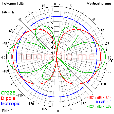
Figure 2 illustrates the relationship between:
- the 0 dBi isotropic radiator (blue),
- one example of a dipole antenna (red) yielding 2.14 dBi,
- the Diamond CP22E introduced in figure 1 (green) putting in an impressive 5 dBi.
If you use the popular water balloon analogy, it isn’t hard to see how squeezing the isotropic sphere at the top and bottom makes a bulge appear to the sides. Here the dipole is 2.14 dB stronger to the sides than the isotropic radiator.
dBd, dBi and good ole’ SI
The proper way to express in decibel values in the International System of Units (SI) units is…
Directivity of dipole = 2.14 dB (re isotropic) [6][8]
…or for those looking to pad their documentation with lots of words…
Directivity of dipole with respect to an isotropic antenna = 2.14 dB [6]
Thankfully the professional antenna field coined the abbreviation dBi by at least 1968 [7] making…
Directivity of dipole = 2.14 dBi
…perfectly fine. For cases where one desires to compare gain to a dipole instead of the isotropic radiator, the proper expression will be…
Directivity of dipole = 0 dB (re dipole) = 0 dBd
…where dBd is another well known shorthand notation for gain with respect to a dipole.
Note the reference dipole is always about 2.14 dB higher (or exactly 2.15 dB higher if you are the FCC) than isotropic so the two are merely a constant value from each other… always. dBi and dBd mean nothing else.
dBx
The various forms of guidance for using SI units discourages, and in the case of NIST prohibits [6], using any additional nomenclature for things like “dB” making well known “slang” terms like dBm, dBV, dBu and for antennas dBi and dBd something to avoid. Pragmatism comes from Horowitz and Hill…
“Although decibels are ordinarily used to specify the ratio of two signals, they are sometimes used as an absolute measurement of amplitude. What is happening is that you are assuming some reference signal amplitude and expressing any other amplitude in decibels relative to it. There are several standard amplitudes (which are unstated, but understood) [for example] dBV – 1 volt rms; dBm – the voltage corresponding to 1 mW into [an] impedance; [. . .] dBrnC (relative noise reference weighted in frequency by ‘curve C).” [8]
…and this…
“When stating amplitudes this way, it is best to be specific about the 0 dB reference amplitude; say something like ‘an amplitude of 27 decibels relative to 1 volt rms,’ or abbreviate ’27 dB re 1V rms,’ or define a term like ‘dBV.’” [8]
Emphasis added.
The point is, if you use dB to represent anything including antenna gain and you reference some specific level, you cannot just say “My antenna’s gain is 12 dB” and not expect to be laughed out of the room. State the reference in some way and you will be good to go.
References
- Cheng, David K. (1983). Field and Wave Electromagnetics. Addison-Wesley Publishing Company.
- Stutzman, Warren; Gary Thiele (1981). Antenna Theory and Design. New York, NY: John Wiley & Sons. pp. 32-40.
- Rec. ITU-R V.574-4.
- 412172 Determining ERP and ERIP, FCC.
- TIA329-B-SEPT-1999 Minimum Standards for Communication Antennas Part I – Base Station Antennas.
- Thompson Ambler; Barry N. Taylor (2008). Guide for the Use of the International System of Units (SI) – NIST Special Publication 811. National Institute of Standards and Technology.
- Ralph W Campbell. Patent US3491361A.
- Horowitz, Paul; Winfield Hill (1989). The Art of Electronics (2nd ed.). Cambridge, Mass.: Cambridge University Press. pp. 16-17.

