In a previous post we debunked the 2 meter 5/4 wave antenna as actually an end-fed full-wave antenna resulting in a poor radiation pattern hardly optimal for terrestrial use. The fix was to turn it into a collinear with the addition of a 180 degree phased stub between the two half-wave sections.
Thus, the 2 meter 5/4 wave antenna is bunk… or is it?
That term 5/4 wavelength keeps popping up in antenna discussions which seems to suggest it has some mystical power to achieve gain. Could this be true? Let’s look at some possible thoughts on this particular length:
- The Extended double Zepp antenna is about 5/4 wavelengths long
- Two 5/8 wave antennas put butt to butt are about 5/4 wavelengths long
- Collinear element spacing can result in a total length of around 5/4 wavelength
- Hmmm…
One common theme among these successful longer-than-a-wavelength systems is they are all fed in the center, not at the end.
Let’s compare center feeding vs. end feeding a 5/4 piece of wire.
First let me preface this simulation with some points…
- This model is very very simplistic
- It does not model the transmission line – it should for the complete picture
- It does not include a matching system at all – a real antenna would
- This is just a simulation of putting a power source at the middle or the end of a 5/4 piece of wire above real ground about 20 feet or so and that’s all
- You should consider getting your own copy of EZNEC or equiv. when you are ready to model your complete antenna system – transmission lines and all
So this very simple simulation takes a vertical piece of wire and puts a source at the bottom end or in the middle to compare what happens to the signal plot above real ground.
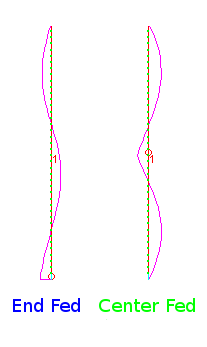
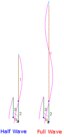
This view reveals the amazing difference in current distribution for each…
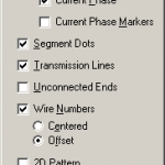 If you are doing this in your own copy of EZNEC remember to select Current Phase from the View Antenna Attributes so you can study the current phase, not just the magnitude.
Note how the End Fed 5/4 wave antenna has two large opposing phases of current. The Center Fed 5/4 wave also has two large current nodes, but they are the same phase… just like a good Collinear Antenna.
If you do not understand why the current phase changes when a long wire is energized with RF put the ARRL Antenna book on your Christmas wish list. It is superb at explaining this.
If you pick up a copy of the ARRL Antenna book and read about collinear antennas, you will find a chart suggesting optimum gain vs. separation of the half-wave elements. You will see the center fed 5/4 wave antenna produces the two primary half-wave in-phase elements at a desirable spacing. The ARRL Antenna book is a must read for any antenna experimenters and designers.
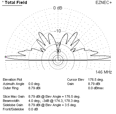
Let’s plot the Center Fed 5/4 Wave Antenna first…
8dBi or so and at a nice desirable low angle perfect for VHF communications.
8dBi??? How can a non-beam antenna have such high gain. Well, remember we are simulating this antenna over real ground and real ground will reflect your signal leading to a maximum towards the horizon. If you simulated this design with “Free Space” selected you would get the more typical 3dB or so gain figures. Because real world situations are important, I usually default my simulations over real ground to ensure I don’t miss something basic. Free Space or over real ground, the point of this article is to highlight the difference in performance between the end-fed and center-fed 5/4 wavelength antenna. For those still wondering, yes a beam will produce still more gain than 8dBi.
Now for the End Fed 5/4 Wave Antenna…
Hurl.
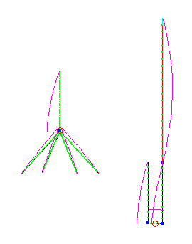
The 5/4 wave antenna up about 20 feet at the base and fed at the end produces an almost 7dBi gain, but 45 degrees above the horizon – hardly useful. This high angle gain comes at the expense of the low angle RF which is still more than 1 dBi. It is possible all the hype over 5/4 wave antennas is reinforced by the fact they will still work with weak gain tricking the user into thinking it is a superior antenna just because it has 5/4 wave in its title.
Why is the same antenna so different depending on where we feed it?
The answer lies in how we manage the two primary half-wave current nodes in the antenna.
If we feed the antenna in the center with, say, a balanced transmission line, one line pushes current while the other pulls current which results in the current direction being the same in the two dominate half-wave current nodes at the top and bottom of the antenna.
On the other hand, if we manage to feed the end-fed antenna at the bottom with the same balanced feed (one line connected to the antenna, the other to some sort of counterpoise) the current phase switches every half wavelength resulting in opposite current nodes.
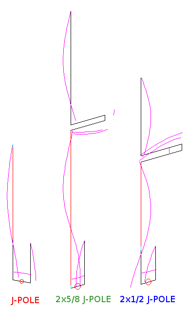
The only way to fix this issue is to feed the antenna in the center or introduce a half-wave 180 degree delay element between the two half-wave current nodes as is done in “double J-Poles” and other Collinear antenna designs.
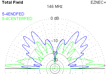
Comparing both antenna patterns…
The vertical end-fed 5/4 wavelength antenna may actually work somewhat for VHF use, but is hardly an efficient use of antenna resources.
If you are going to put all the effort into a large cumbersome antenna design you are well advised to:
- Read the ARRL Antenna Book.
- Model your antenna in EZNEC – a limited free version is available.
- Be suspicious of any web site promoting amazing performance with any single antenna element longer than 5/8 wavelength.
- Model your transmission line, too, when doing your final simulations – you will be surprised how it affects your signal.
- Understand great SWR is great, but has little to do with antenna patterns and performance.
Antenna experimentation and design is a fascinating part of our Amateur Radio hobby and well worth the time and expense. However, you will find far more enjoyment in this endeavor if you read up on antenna theory at least a little first and then try your designs in the free version of EZNEC second. This will help you avoid the woodchuck mistakes leading to far more enjoyment of your hobby.

Based on that radiation pattern, the end-fed 5/4 wave antenna might be ideal for satellite comms…
It could provide some coverage for sats going almost over your head, but most of the time they fly by low to the horizon. What I have seen for sat antenna solutions is Turnstiles and Lindenblads which concentrate a large about of energy towards the horizon and a little above. The Turnstile has a nice smooth gain curve from near horizon to zenith.
I find the following remarks revealing of your thinking. "The 5/4 wave antenna up about 20 feet at the base and fed at the end produces an almost 7dBi gain, but 45 degrees above the horizon – hardly useful. This high angle gain comes at the expense of the low angle RF which is still more than 1 dBi. It is possible all the hype over 5/4 wave antennas is reinforced by the fact they will still work with weak gain tricking the user into thinking it is a superior antenna just because it has 5/4 wave in its title." "The vertical end-fed 5/4 wavelength antenna may actually work somewhat for VHF use, but is hardly an efficient use of antenna resources." It seems you are ignoring the repeater user in this article, who often benefit from a higher angle of radiation due to repeaters being several thousand feet higher on mountain tops!. For me (and them) the end fed version is far superior to the center fed version. I would verture a guess that we are in the majority. Otherwise your article is good and has useful information.
If you do the trigonometry it is true repeater users against the mountain deal with a high elevation angle. Using your example repeater height of 3,000 (several thousand) feet we have:
1/2 mile away – 49 degree elevation angle,
1 mile away – 30 degree elevation angle,
2 miles away – 16 degrees elevation angle,
5 miles away – 6 degrees elevation angle,
10 miles away – 3 degrees elevation angle,
20 or more miles away – less than 2 degrees elevation angle.
Much depends on the purpose and service area of the repeater. I venture to guess most repeater sponsors desire to service a large area on the order of 10 to 30 mile max radius… or perhaps more.
If the user is close to the repeater, a high angle with low or no gain antenna will suffice. A simple 1/4 wave ground plane or even a rubber duck antenna and 1/2 watt should be more than adequate.
If the user is a few miles or more away, an antenna with higher gain and lower take off angle begins to make sense.
The 5/4 wave antenna provides higher gain at higher elevation angles which doesn't fit the repeater user scenarios above. I argue the 5/4 wave antenna is not an ideal use of resources for the typical repeater user.
Forget 450°or 5/4…. 115° per element is the way to go centre fed of course…
or the big daddy of them all is 230° (EDZ)per element, but remember all elements
must be measured with supreme accuracy or your wasting your time…
And yes we are talking about vertical antennas.
very good…forget the arrl yours is very informative and well explained 73s
I would love to see your comments about the SlingShot VHF antenna.
Two vertical half-waves spaced half-wave and bottom feed.
73!