In a recent email from the ARRL concerning ARES topics, a writer compares the coaxial vertical dipole antenna with a J-Pole for VHF work. He says…
“With no real models for comparison, it is difficult to compare patterns for each antenna. I would suspect that the J-Pole would not have an omni-directional pattern and would therefore produce a lobe or lobes giving gain in some directions”
Really?
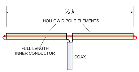
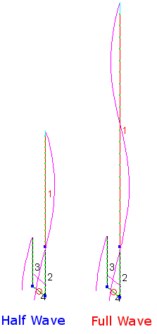
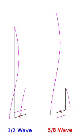
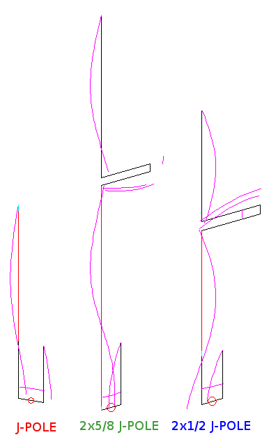
Larry Cebik’s antenna model collection contains hundreds of antennas to examine with NEC or EZNEC and the J-Pole is no exception. However, I did not find a coaxial antenna in his models. So I examined the original patent for the Coaxial Dipole antenna and found it was originally composed of several elements running parallel to the coax to provide the bottom half of the dipole. Great. The models for the J-Pole, the coaxial dipole and a reference typical monopole with 45 degree radials are shown below…
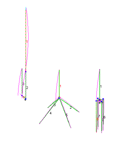
All three examples are simulated with their feed points at 300 inches above ground. The J-Pole enjoys a height advantage for obvious reasons. This advantage become more pronounced at lower elevations since the J-Pole’s height delta is a larger percentage of height above ground the lower the overall height is.
Height increases gain for all three antennas as the ground reflection begins to focus the horizon bound energy. No real surprise there. It is the relative gain patterns we really care about here. Here it is for Azimuth at an elevation about 3.5 degrees…
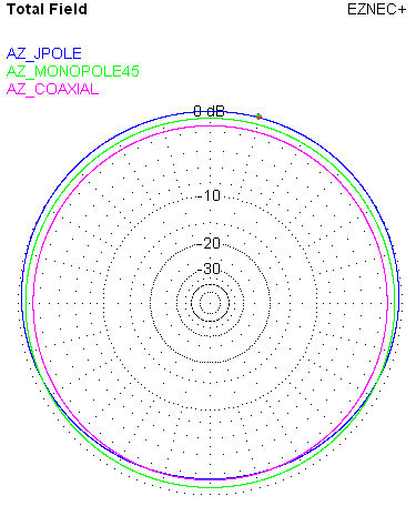
Indeed, you can see the J-Pole’s lack of perfect symmetry results in a slight benefit in certain directions as correctly assumed by the ARES article author. However, the difference is not very significant at less than 3 dB. Also, there are no lobes of gain or loss, in azimuth, like the author theorizes. Lobes do exist for elevation for all three antennas.
Here is a comparison of elevation…
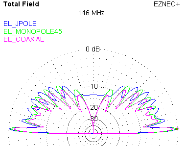
The J-Pole enjoys the most gain at around 6 dBi with the other two antennas pretty close to this value. Again, all three antenna’s gain is very dependent on the height above ground. Thus, the J-Pole always has a slight advantage. Otherwise, the J-Pole is just a half-wave radiator like the coaxial dipole with a slight height advantage.
What are we to make of all this? Well, don’t listen to anyone who tells you one antenna is dramatically superior in performance to another. In the end, they all, more of less, behave like a half-wave radiator and all are a little better than a 1/4 wave monopole over horizontal radials.
The Monopole is the one that bests matches to 50 ohm coax thanks to the angled radials. The coaxial dipole simulates to around 80 ohms impedance which is close to the 72 ohm half-wave value. The J-Pole feed is, indeed, a bit complicated, but matches 50 ohms very well.
So put performance issues aside and concentrate only on the mechanical issues when selecting your next VHF antenna.
Also, you now know better if someone tells you there are no real models for comparison. Simulation has its limits, but is an excellent first step. You can rest assured an antenna invented in the 1930s has been modeled at least once.
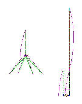
With regards to the coax dipole, how many sources are you using?
Are the 4 external legs connected to the center conductor or the shield?
I ask as I'm attempting to model a popular 910mhz ant used in RC airplanes to transmit video. The ant is nothing but a piece of turtle necked coax, with 1/4 of center conductor exposed and a 1/4 wave of the coax insulation turned back on itself.
When I modeled this, it gets ugly.. I was refered to this web page, which shows a coaxial dipole, but I wonder if we are working on the same idea or not..
Thanks for your time
James Lerch
Tampa, FL
Hello James,
In the coaxial dipole EZNEC model I have one source at the bottom end of the upper element. Actually this source position is automatically centered in the bottom most segment as I recall. For simulation purposes only, the four wires for the external legs are all attached to the bottom of the top wire.
One thing you should add to make the simulation more complete is the addition of one more wire also attached to the bottom of the top wire. This simulates the outside of the coax braid to some extent and reveals why these antennas can be difficult.
I design 900 MHz antennas for our UAV airplanes and I had to use a couple of ferrite cylindrical beads around the coax just beneath the lower extent of the four wires to "choke" the current from flowing further down the coax. If I don't do this, the whole coax becomes part of the antenna. Your description is apt… it gets ugly.
Folding back the braid keeps things simple, but you still need to choke that current on the rest of the coax to get what you want.
Sounds like you are on the right track. Good luck.
John
Gentlemen:
I've done a fair amount of modeling and of building bazooka (similar to coaxial) and end fed Zepp (similar to jpoles) antennas over the last few years. I'd like to point out that of the three antennas modeled above, the jpole is the easiest to construct and has the fewest problems with feed line current.
To be complete, the feed line should be included in the models. One quickly sees that, even with a perfect choke at the base of the coaxial antenna, significant feed line currents are generated. The monopole has less of a problem and the jpole has nearly none.
Great article!
ward
Edward,
You are of course correct the feedline should always be the next step in modeling after the primary radiation characteristics are understood. The mounting structure should be modeled as well. All three antenna variations suffer feedline/structure currents with the J antenna certainly being the worst of the lot. I discuss this quite a bit here…
http://www.hamradio.me/interests/j-pole/