Background of 40m Loop
Two years ago I installed a full wave 40m loop wire antenna in preparation for the Virginia QSO Party. The goal was burning clouds with RF to facilitate local contacts. The loop is pretty low and inefficient, but on the air tests confirm the preference for high angle skywave vs. DX capability. It does a great job reducing interference from shortwave stations.
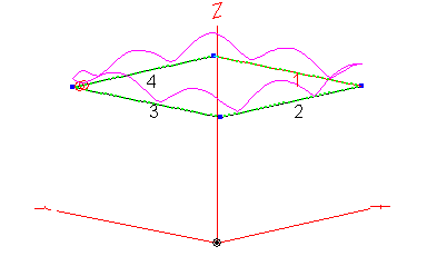
I used NEC to design the loop dimensions and this worked out quite well.
Most of us understand the impedance of a full wave loop is something on the order of 100 ohms. This reduces a bit when you get near lossy ground. One thing I did while using NEC was introducing another wire just above ground level to improve ground conductivity. NEC suggests this extra wire yields a small increase in gain straight up. However, the real benefit of this wire for me was the reduction of the feedpoint impedance to 50 ohms.
A benefit of fullwave loops in general is their tendency, at least at the center frequency, to not require a balun. My tests suggest this is true.
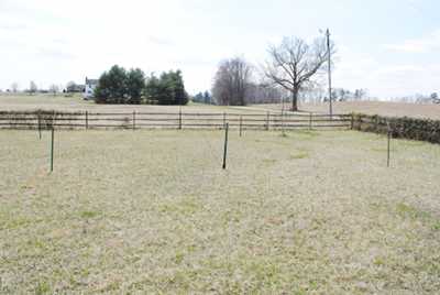
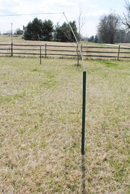
Two years ago with minutes to spare, I put up the antenna using Tractor Supply fencing materials to support the four corners and a fifth one to support the feedpoint – in the middle of the square in my case.
In my case the “ground” wire lays on the ground and is well grown into the grass. The active loop element is a droopy thing with an average height of 4 feet or so.
Results using 40m Fullwave Horizontal Loop
I used the loop off and on over two years with reasonable success in QRP Fox Hunts and other misc. events. My 43 foot vertical and this fullwave horizontal loop make a complementary pair of 40m antennas to facilitate local vs. long distance contacts. The 43 foot reigns supreme at efficient transmitting so I often transmit with it and receive with loop. Antenna choices are good thing.
QRP suggests the loop works well enough
Yesterday I took my QRP rig out to the antenna, connected it, and made an easy 40m Phone QSO with some net in CT. Subjective as this is, he had me S5 from my 5 watts in Virginia.
All the above is really not the point of this post, but sets the stage. It’s a 40m loop low over a ground wire and actually works.
Here it is two years ago…
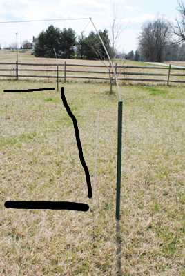
The black line shows where the ground wire sits in the grass. Here is the 50 ohm SWR of the 40m full wave loop above that ground loop wire…

Not too shabby. However, I did wonder if my 130+ feet of copper wire in the soil really had any effect on the antenna.
Does the ground wire have any effect?
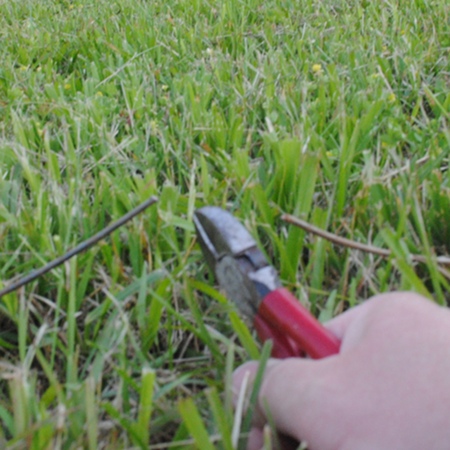
In the name of science I retook the SWR measurement after cutting the wire to detune it…
…to yield this comparative plot of SWR…
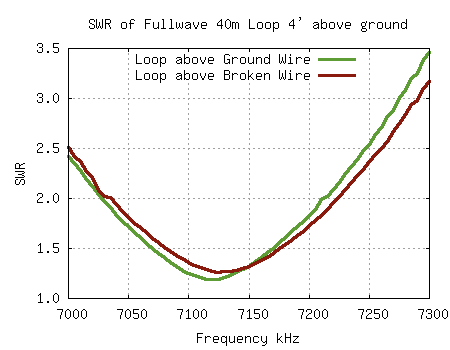
Hmmm, it does change ever so slightly. Let’s have a better look using Return Loss…
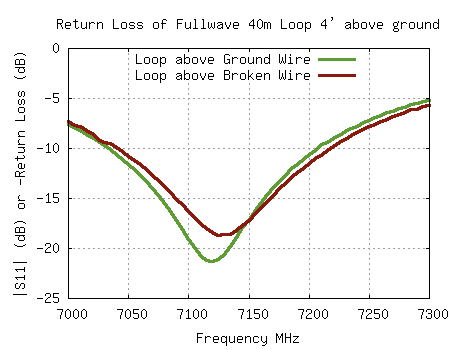
There are two things to notice in this 50 ohm VNA data…
- The frequency shifts up a little when the ground wire is broken.
- The dip of Return Loss is a bit less when the wire is broken.
Without the ground wire the antenna seems to have a slightly lower Q suggesting the impedance of the ground is higher than with the ground wire laid upon it. This makes sense, but is nice to have some real data to confirm.
Final thought
At the end of the day the ground wire laid underneath the 40m full wave loop doesn’t make a whole lot of difference in feedpoint impedance measurements. However, it doesn’t hurt and does improve the antenna system a little bit… simulations suggest a few dB improvement. Is it worth the additional length of wire. To me it is. Others have to decide for themselves. As always in engineering and amateur radio… Better is the Enemy of Good Enough.
Note there are much better NVIS antennas out there, one being this same horizontal loop higher above ground… say 30 feet or so. The beam shape is almost the same, but the gain is several dB more straight up. Any higher and the antenna grows DX loving low angle gain. Never make the mistake low NVIS antennas are efficient… they are quite lossy compared higher alternatives.
